Electrical connector assembly

a technology of electrical connectors and components, applied in the direction of coupling device connections, incorrect coupling prevention, engagement/disengagement of coupling parts, etc., to achieve the effect of preventing accidental misalignment or bending of the protruding blades, repeatability and low cost stabilizers

Inactive Publication Date: 2005-01-25
DELPHI TECH INC
View PDF30 Cites 40 Cited by
  • Summary
  • Abstract
  • Description
  • Claims
  • Application Information

AI Technical Summary

Benefits of technology

An advantage of the present invention is a robust and low cost stabilizer which is automatically retractable and thus is repeatably reusable during the mating and un-mating process of the electrical connector assembly. Another advantage of the present invention is the prevention of accidental mis-alignment or bending of the protruding blades of the male terminals of an electrical connector assembly being re-mated. Yet another advantage of the present invention is the elimination of foreign article or debris collection within the blind bore of the male connector which could prevent fill re-mating of the electrical connector.

Problems solved by technology

However, this tight fit is not strong enough to force the stabilizer out of the pre-staged position in such a fashion that the stabilizer becomes completely removed from the blind bore of the male connector.

Method used


Image

  • Electrical connector assembly
  • Electrical connector assembly
  • Electrical connector assembly

Examples


Embodiment Construction

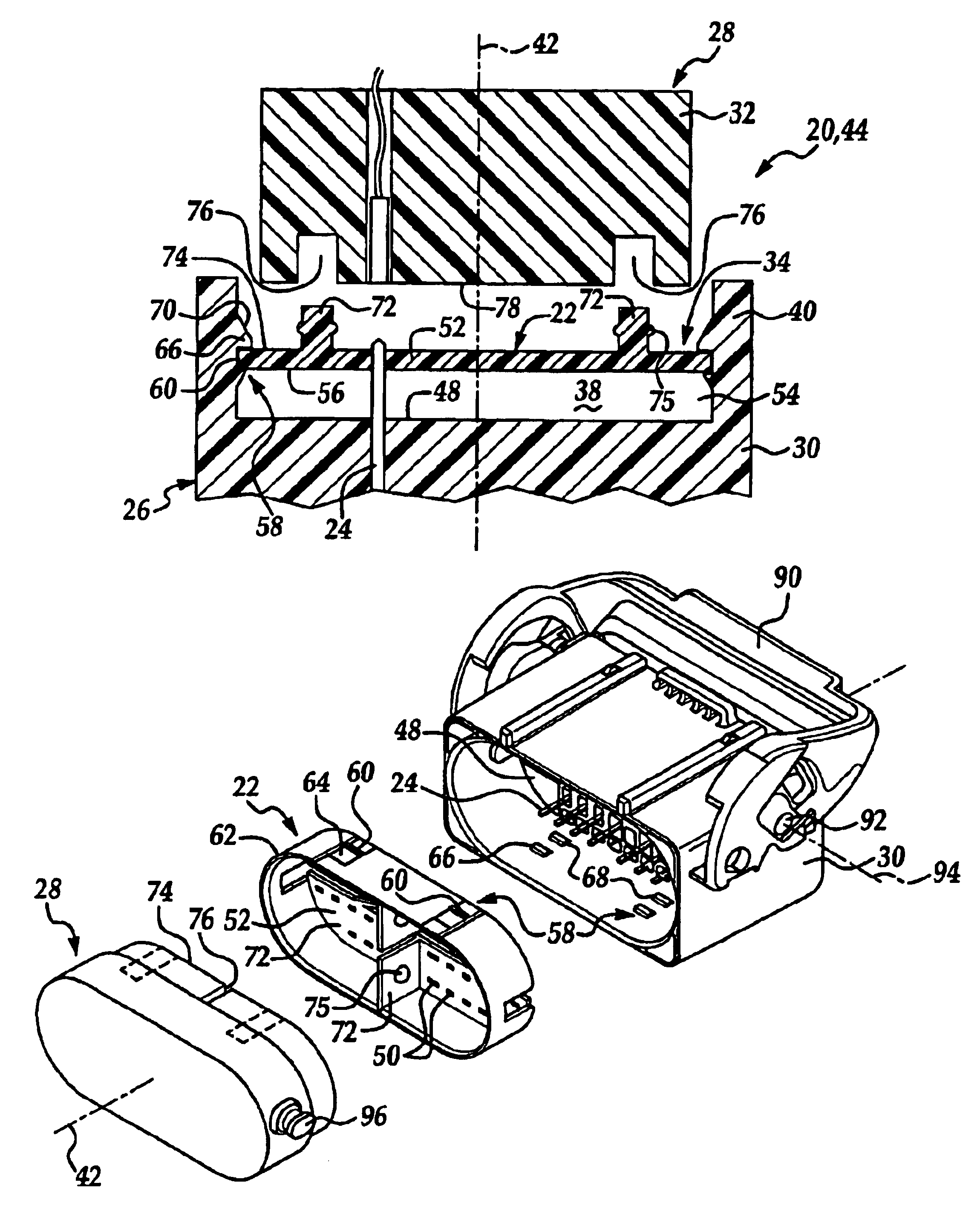
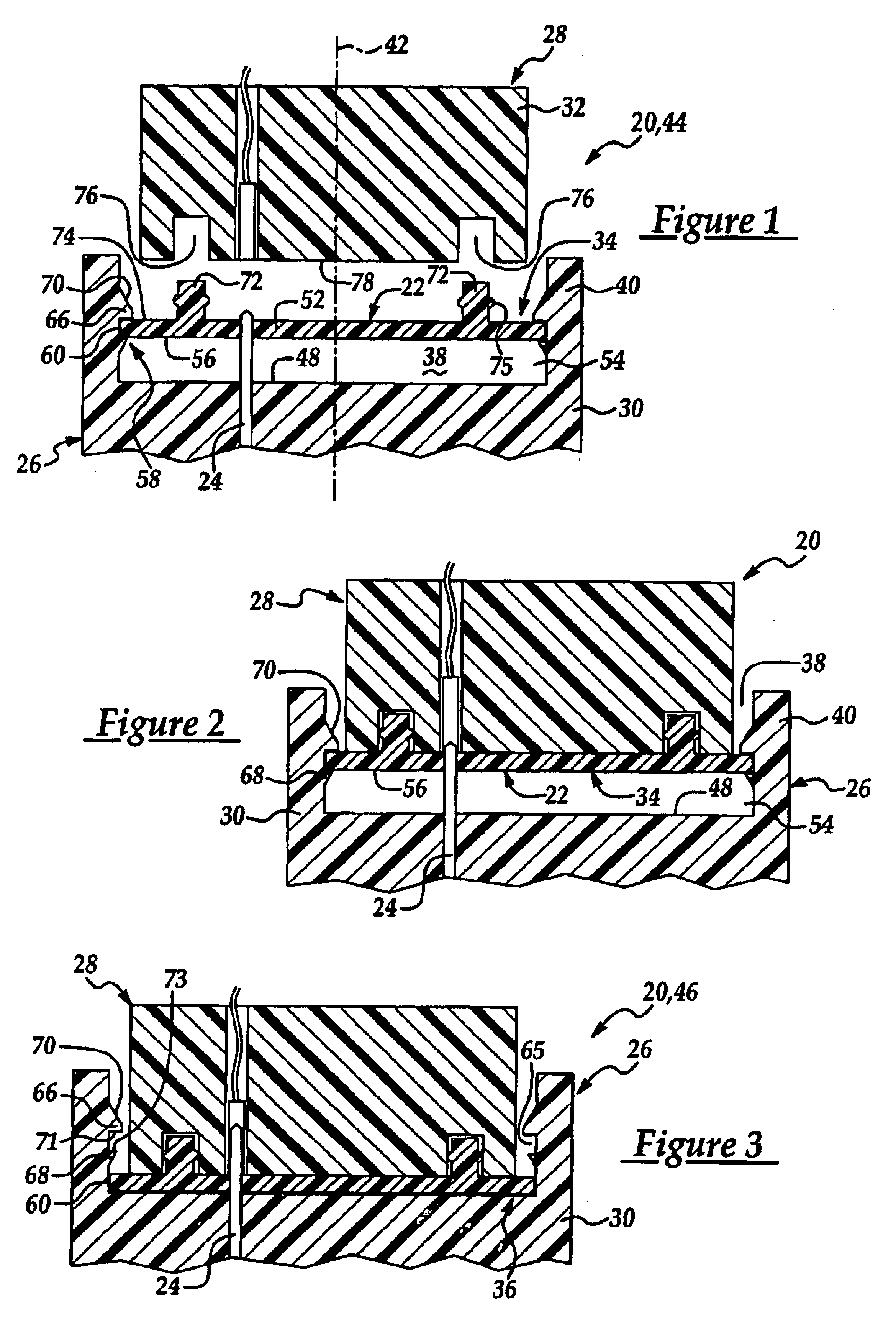
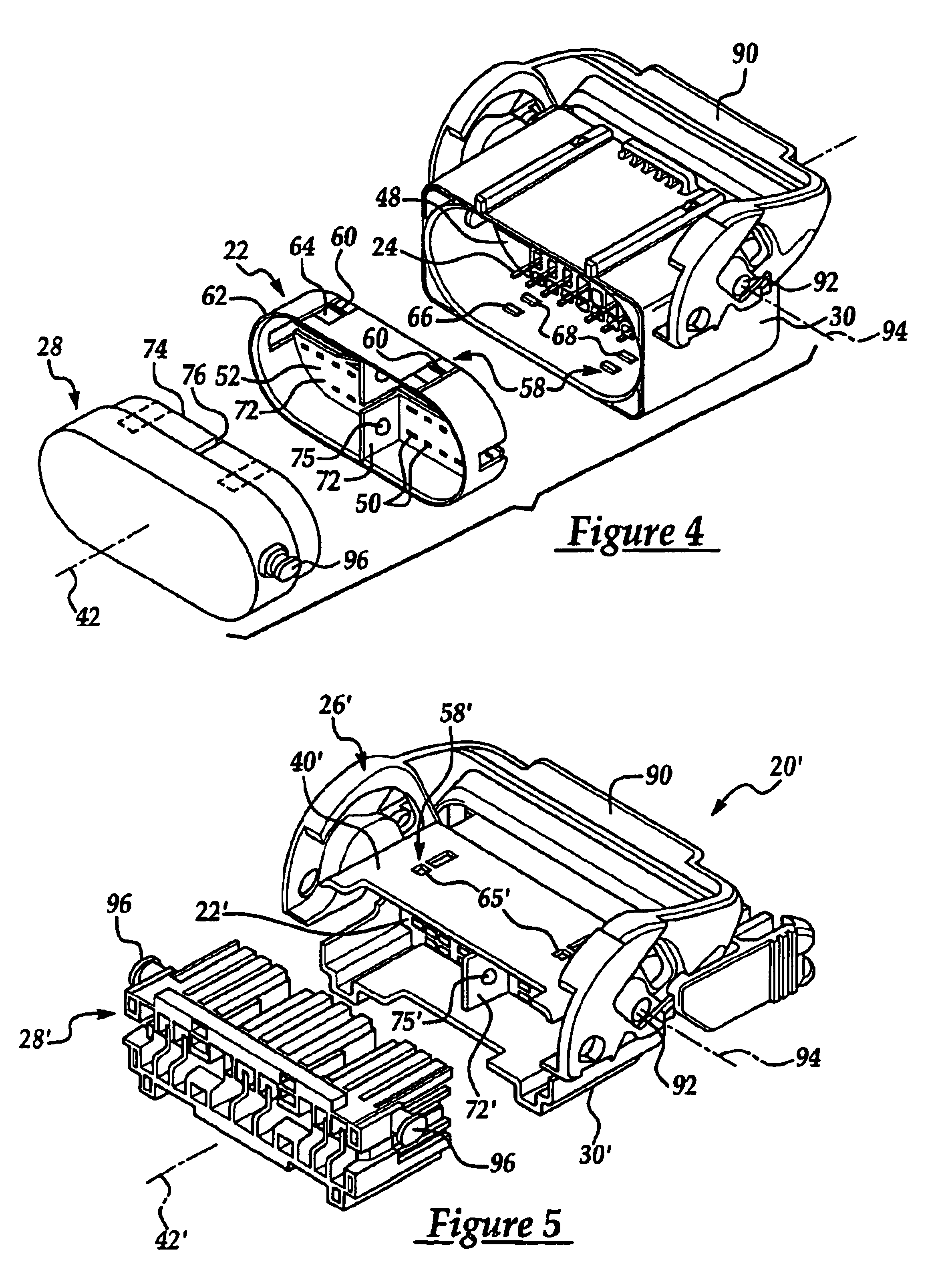
Referring now to the drawings, FIGS. 1-3 illustrate a multi-pin electrical connector assembly 20 having a self-aligning, dual-positioning, pin or blade stabilizer 22 for ensuring a reliable and a repeatably mateable electrical connection. The blade stabilizer of the assembly protects a series of terminal blades 24 of a male connector 26 prior to mating of the male terminals or blades 24 to a series of non-ferrous contacts or female terminals of a female connector 28. In addition, because the male terminals 24 are locked to a male connector body 30 and are known to rock or laterally move slightly with respect to the body, the blade stabilizer 22 acts to pre-align distal tips of the male terminal blades for mating to the female terminals (not shown) of the female connector 28. The stabilizer 22 is generally disposed between the plastic body 30 of the male connector 26 and a plastic body 32 of the female connector 28 which carries the female terminals.

Unlike conventional blade stabiliz...


PUM


Abstract

An electrical connector assembly has a male connector which mates to a female connector thereby electrically engaging male terminal blades, locked to a male connector body, to female terminals locked to a female connector body. The blade of each male terminal project into a blind bore defined by a shroud of the male connector body. Prior to mating of the electrical connector assembly, a retractable terminal blade stabilizer is snap fitted into a blade alignment position with the male connector via a dual fastening feature constructed and arranged between the male connector body and the stabilizer, which prevents withdrawal of the stabilizer from the male connector and restricts further insertion of the stabilizer into the blind bore. When the stabilizer is in the blade alignment position, the tips of the blades are disposed within respective apertures of the stabilizer and aligned to their respective female terminals and the remaining portion of the blades are shielded and thus protected from possible damage. During mating of the electrical connector assembly, the female connector body is press fitted to an axial projecting member of the stabilizer, prior to the stabilizer moving out of the alignment position.

Description

TECHNICAL FIELDThe present invention relates to an electrical connector assembly, and more particularly to an electrical connector assembly having a retractable terminal blade stabilizer.BACKGROUND OF THE INVENTIONElectrical connector assemblies are know to have a male connector which mates to a female connector thereby electrically engaging respective male terminal blades to female terminals. The blade of each male terminal may extend axially into a blind bore defined by an axially projecting shroud of the male connector body. Prior to mating of the electrical connector assembly, a conventional self-aligning blade stabilizer is known to be snap fitted into a blade alignment position within the blind bore of the male connector via a dual locking feature which prevents withdrawal of the stabilizer from the male connector and restricts further insertion of the stabilizer into the blind bore from the blade alignment position and toward a fully seated position. When the stabilizer is in...

Claims


Application Information

Patent Timeline
Patent Type & Authority Patents(United States)
IPC IPC(8): H01R13/629H01R13/453H01R13/52
CPCH01R13/4538H01R13/62938H01R13/5213
Inventor HOBBS, JON C.MORELLO, JOHN R.
Owner DELPHI TECH INC
Why Eureka
Try Eureka