Fuel injector and method for controlling fuel injectors

a technology of fuel injectors and fuel injectors, which is applied in the direction of electrical control, process and machine control, instruments, etc., can solve the problems of expensive fabrication of bores, and achieve the effects of avoiding costs, accurately predicted and controlled, and avoiding the risk of fuel leakage and mechanical failure at the si

Inactive Publication Date: 2009-06-30
DELPHI TECH IP LTD
View PDF5 Cites 33 Cited by
  • Summary
  • Abstract
  • Description
  • Claims
  • Application Information

AI Technical Summary

Benefits of technology

[0024]The present invention also offers advantages when compared to providing intrusive pressure sensors in individual injectors. According to the invention, the pressure sensor is separated from the supply passage, so there is no need for a precision-machined bore or breach in the supply passage within the injector. Such a bore would be expensive to fabricate and would provide a site for potential leakage or mechanical failure. Furthermore, the pressure sensor is not subject to the high-pressure environment of the supply passage. This reduces the risk of mechanical failure of the sensor, and because the sensor need not be engineered to resist high pressures, the cost of the sensor can be minimised. Similarly, because the sensor need not be leak-proof, the design of the pressure sensor can be relatively straightforward, resulting in a robust and low cost device. For example, high-pressure seals are not required.
[0037]A rail fuel pressure sensor need not be provided, so avoiding the costs of the rail pressure sensor itself, and of providing a precision-machined bore in the fuel rail for mounting the rail pressure sensor. Furthermore, by eliminating the breach in the fuel rail required to accept the sensor, the risk of fuel leakage and mechanical failure at this site is avoided.
[0039]By providing a fuel pressure sensor within each injector, measured values of the fuel pressure in each injector can be obtained and input to the control unit or ECU. The ECU can use these measured injector fuel pressure values to calculate the injection duration for each injection event, rather than relying on an estimated injector fuel pressure based on measured values of the rail fuel pressure remote from the injector as in conventional systems. In this way, the quantity of fuel delivered in an injection event can be more accurately predicted and controlled.
[0043]By predicting the fuel pressure that will prevail in a fuel injector over the course of a forthcoming injection event in this way, the amount of fuel injected during the injection event can be more accurately controlled than would otherwise be possible, and accurate control can be achieved for all engine operating conditions and injection strategies.
[0061]Again, a degree of robustness against sensor failure can be provided in accordance with another aspect of the invention, which resides in a method of predicting a fuel pressure characteristic in a fuel injector of a fuel injection system during an injection event, the method comprising measuring, before the injection event, fuel pressure characteristics within a plurality of fuel injectors, detecting an erroneous pressure signal from one injector of the plurality, and excluding the erroneous pressure signal from prediction of the fuel pressure characteristic.

Problems solved by technology

Such a bore would be expensive to fabricate and would provide a site for potential leakage or mechanical failure.

Method used


Image

  • Fuel injector and method for controlling fuel injectors
  • Fuel injector and method for controlling fuel injectors
  • Fuel injector and method for controlling fuel injectors

Examples


first embodiment

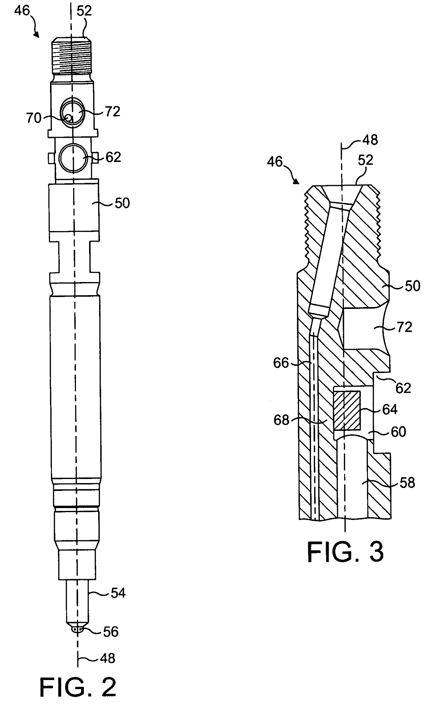
[0082]FIGS. 2 and 3 show an exemplary fuel injector 46 according to the present invention. FIG. 2 is a side view of the elongate injector 46 showing its longitudinal axis 48. FIG. 3 is an enlarged detailed view of the injector 46 in longitudinal section taken parallel to the longitudinal axis 48 of the injector 46.

[0083]The injector 46 comprises a generally cylindrical injector body 50 which, in use, extends through a cylinder head of an internal combustion engine. The upper part of the injector body 50 is provided with a fuel inlet 52, which receives high-pressure fuel from a common fuel rail (not shown). The lower part of the injector body 50 comprises a nozzle 54 arranged to inject fuel into a combustion chamber of the engine.

[0084]As is well known in the art of fuel injectors, the nozzle 54 houses a valve needle moveable between two positions. In a first, closed position, the needle seals against a seating surface of the nozzle 54 to prevent the flow of fuel through one or more ...

second embodiment

[0103]A sensor chamber 122 is provided within the injector body 112, above the inclined portion 116 of the supply passage 110. A threaded port 124 connects the sensor chamber 122 to the uppermost, top surface of the injector 108. As in the invention, a magnetostrictive pressure sensor 82 comprising a core 84 and a coil 90 is provided in the sensor chamber 122.

[0104]The distal end face 88 of the core 84 is located close to the inclined portion 116 of the fuel supply passage 110, in a region 126 where the inclined portion 116 has an enlarged diameter. The enlarged diameter region 126 may, for example, accommodate a filter or a flow-conditioning device (not shown). The pressure sensor 82 is inclined to the longitudinal direction of the injector 108, so that the distal end face 88 of the core 84 lies parallel to the side wall of the enlarged diameter region 126 closest to the sensor 82.

[0105]The pressure sensor 82 is held in position by a clamp screw 128 located in the port 124. Like th...


PUM


Abstract

A fuel injector for an internal combustion engine, the fuel injector comprising an injector body, a fuel supply passage defined in the injector body, the fuel supply passage containing fuel under high pressure in use of the injector, a pressure sensor for measuring the pressure of fuel in the passage in use, wherein the pressure sensor is situated within the injector body and is separated from fuel in the passage in use, and a method of fuel injection, comprising constructing an hydraulic behavior profile by fuel pressure measurement, using the hydraulic behavior profile to predict fuel pressure that will prevail in a fuel injector during an injection event, and supplying a control signal to the fuel injector to control the amount of fuel injected during the injection event in accordance with the predicted fuel pressure. By predicting the fuel pressure that will prevail during an injection event, the fuel delivered during the injection event can be accurately controlled.

Description

TECHNICAL FIELD[0001]This invention relates to fuel injectors for internal combustion engines, and methods for controlling the quantity of fuel delivered by fuel injectors. In particular, the invention concerns the determination or prediction of the pressure of fuel in a fuel injector over the course of a fuel injection event.BACKGROUND OF THE INVENTION[0002]Fuel injection systems allow control and optimisation of the quantity of fuel injected into the combustion chambers of an engine, the timing of fuel delivery with respect to the crankshaft and piston position, and the presentation of fuel to the combustion chamber, for example by atomising and dispersing the fuel in a pre-determined pattern. Modern fuel injection systems use electronic controls to achieve a high level of precision in the quantity and timing of the fuel delivery. This high precision is required to meet emissions and performance expectations of the marketplace.[0003]Common rail fuel injection systems are well know...

Claims


Application Information

Patent Timeline
Patent Type & Authority Patents(United States)
IPC IPC(8): F02D41/30F02D28/00
CPCF02D41/3827F02D41/40F02M61/168F02D41/2467F02D2041/1433F02D2200/0602Y02T10/44F02M2200/21F02M2200/24F02M2200/8092F02D2200/0604F02M57/005F02M2200/247Y02T10/40
Inventor DINGLE, PHILIP J. G.
Owner DELPHI TECH IP LTD
Why Eureka
Try Eureka