Metal seal

a technology of metal seals and metal rings, which is applied in the direction of engine seals, borehole/well accessories, constructions, etc., can solve the problems of metal used in seals that may experience tension beyond the yield strength of the material in the seal, the seal may have altered its shape, and cannot function properly, so as to soften the seal ring surface metal in place

Active Publication Date: 2015-10-06
AKER SOLUTIONS AS
View PDF17 Cites 0 Cited by
  • Summary
  • Abstract
  • Description
  • Claims
  • Application Information

AI Technical Summary

Benefits of technology

[0014]Thus, the invention provides a seal ring which can be used under high pressure conditions without risk of permanently altering its shape. The softer seal ring surface metal makes it unnecessary to provide an inlay in the circular sealing surfaces of the annulus which is softer than that of the main metal section of the seal ring. Hence, costly fabrication of the large units, such as a tubing hanger and stinger, against which the seal assembly is adapted to seal, is avoided, since a particular inlay of a hard material will not have to be provided.
[0017]When in a sealing position, one or both of the two legs of the main metal section will preferably exhibit a part of the leg which is without contact to a surface of said annulus. This is, at least partly, a result of a short entering distance. A short entering distance for the seal ring into the sealing position reduces wearing and the risk of scratches on the sealing surfaces.

Problems solved by technology

One of the challenges of such seals is that the metal used in the seal may experience tension beyond the yield strength of the material in the seal.
Thus, when a pressure is removed the seal may have altered its shape, and may not be able to function properly with the next or a later exposure of high pressure.

Method used


Image

  • Metal seal
  • Metal seal
  • Metal seal

Examples


Embodiment Construction

[0018]In the following, a preferred example of embodiment will be described with reference to the accompanying figures, in which

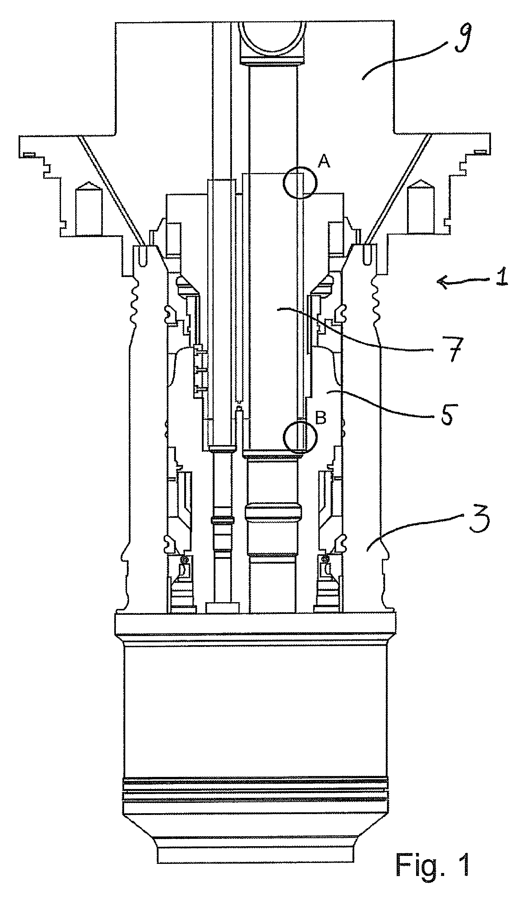
[0019]FIG. 1 is a cross section view of a part of a well assembly, comprising a seal assembly according to the invention;

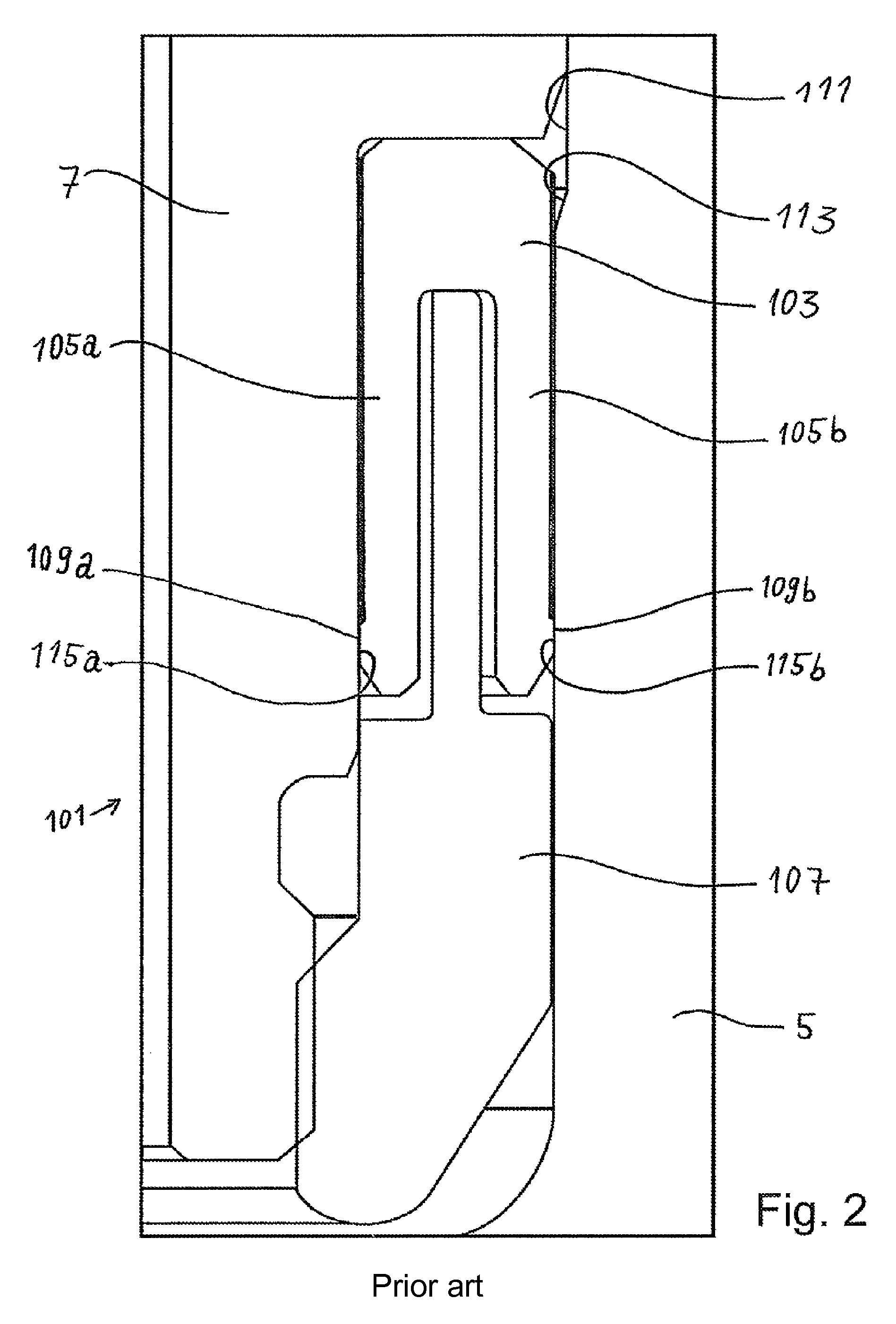
[0020]FIG. 2 is a cross section view of a known seal assembly; and

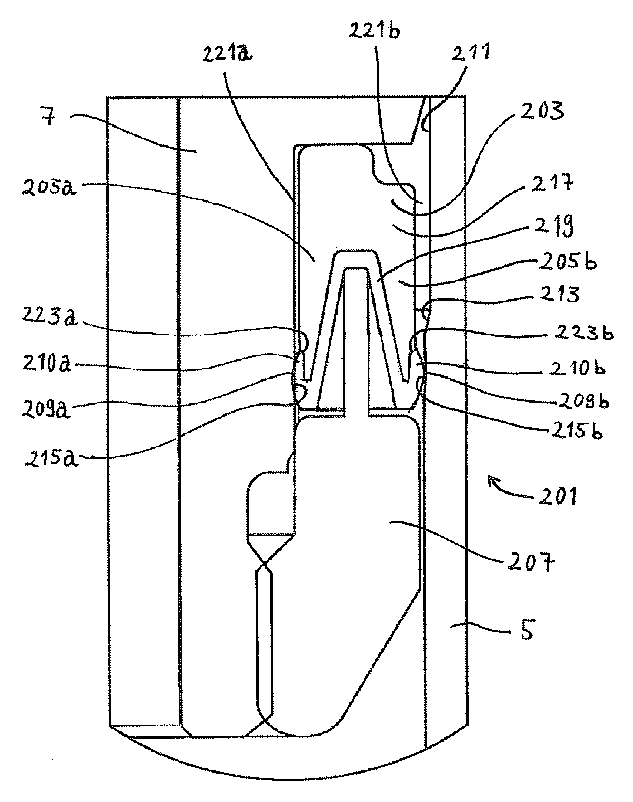
[0021]FIG. 3 is a cross section view of a seal assembly according to the present invention.

[0022]FIG. 1 shows a subsea well assembly 1. It has a well head 3 into which is arranged a tubing hanger 5. Into a bore of the tubing hanger 5 extends a stinger assembly 7. The stinger assembly 7 also extends into a bore of a Xmas tree spool body 9 at its upper end. In the positions A and B, the stinger assembly 7 is sealed to said bores with a seal assembly according to the present invention. Such a seal assembly is shown in FIG. 3.

[0023]FIG. 2 shows a seal assembly 101 known from prior art. The assembly has a seal ring 103 comprising two legs 105a and 105b. The seal ring 103 is held...


PUM


Abstract

Seal assembly (201) for a subsea well assembly with inner and outer circular sealing surfaces (215a, 215b) in an annulus (211). It has a seal ring (203) with a cross section exhibiting two legs (205a, 205b), with seal ring seal surfaces (209a, 209b). The seal ring comprises a main metal section (217) having metal with the same or higher degree of hardness than the metal in said facing circular sealing surfaces (215a, 215b). The seal ring seal surfaces comprise a seal ring surface metal (210a, 210b) which is of a softer metal than the metal in the circular sealing surfaces (215a, 215b) and the metal in the main metal section (217). The seal ring (203) comprises a second section (219) comprising said seal ring surface metal (210a, 210b), the second section (219) extending continuously between said seal ring seal surfaces (209a, 209b) on the respective legs.

Description

[0001]The present invention relates to a metal-to-metal seal assembly for sealing between circular members of a subsea well assembly.BACKGROUND[0002]In the field of subsea wells, the requirement of pressure ranges of the well assemblies is continuously increasing. This leads to corresponding increased technical requirements of the seal assemblies employed in such wells.[0003]Metal-to-metal seals have been used for a long time with various designs. One of the challenges of such seals is that the metal used in the seal may experience tension beyond the yield strength of the material in the seal. Thus, when a pressure is removed the seal may have altered its shape, and may not be able to function properly with the next or a later exposure of high pressure. Hence, one wants to use a sealing member which shape is not permanently altered after exposure to a high pressure.[0004]Further, a standard or prerequisite is that the metal in a sealing member, such as a sealing ring, is softer than...

Claims


Application Information

Patent Timeline
Patent Type & Authority Patents(United States)
IPC IPC(8): E21B33/04F16J15/32E21B33/00F16J15/08
CPCE21B33/04F16J15/3236E21B2033/005F16J15/0806E21B2200/01
Inventor TELLISKIVI, TANELSMITH, ANDRE M.AMREN, BIRGIR
Owner AKER SOLUTIONS AS
Why Eureka
Try Eureka