
Press felt and method for its production

a technology of press felt and production method, which is applied in the field of press felt, can solve the problems of further reducing the internal hollow space volume, reducing the water absorption capacity, and reducing the internal volume of the press felt, so as to facilitate the production. the effect of handling

Active Publication Date: 2009-10-01
VOITH PATENT GMBH
View PDF9 Cites 1 Cited by
  • Summary
  • Abstract
  • Description
  • Claims
  • Application Information

AI Technical Summary

Benefits of technology

[0013]Based on the fact that the first threads and the second threads hold each other in position during the formation of a textile surface structure, the threads of the cross reinforcement layer having to move aside for each other is clearly obviated, resulting in that the internal hollow space volume of the press felt can be maintained also when running through a press nip.
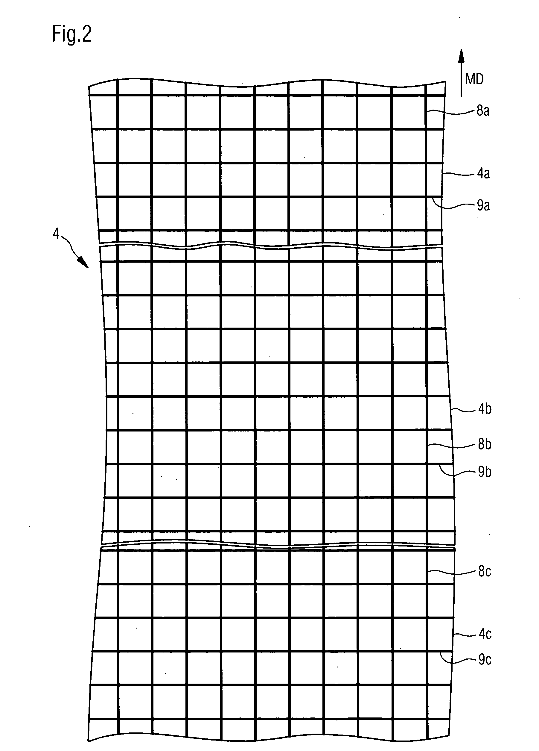
[0080]With the inventive method it is easily possible to produce the cross reinforcement module from a web which is supplied in roll form. Thereby, the expensive fabrication of individual cross module reinforcement segments can be eliminated. The inventive method according to this aspect is especially advantageous when a mesh-type textile surface structure which was produced from first and second threads, crossing each other, is used as the cross reinforcement module, since textile surface structures of this type can be purchased as a fabricated bulk product, in roll form.

Problems solved by technology

A disadvantage of these structures is that such laid structures often only provide a very limited internal volume in the press felt.
Also, since the laid structures of longitudinal and cross threads can move against each other they move aside for each other when running through the press nip, which can lead to a further reduction of the internal hollow space volume and consequently to a reduction in the water absorption capacity.

Method used


Image

  • Press felt and method for its production
  • Press felt and method for its production
  • Press felt and method for its production

Examples


Embodiment Construction

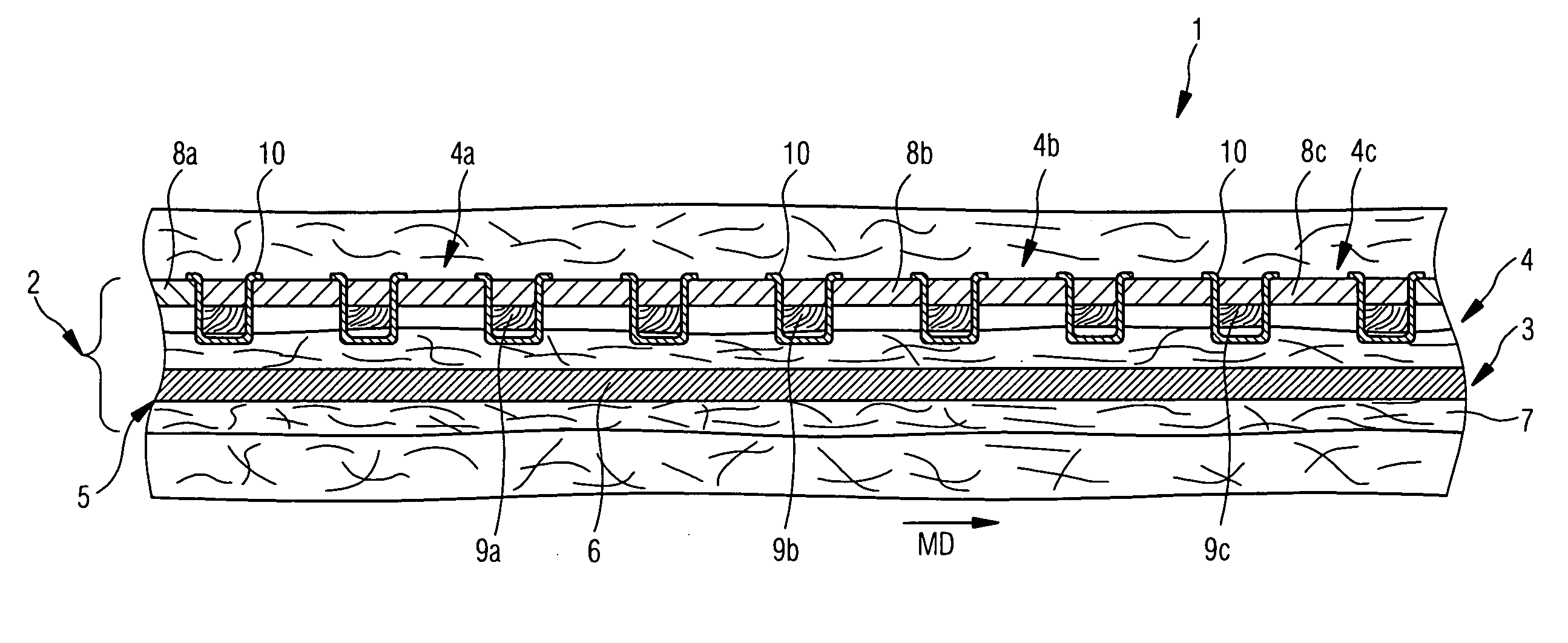
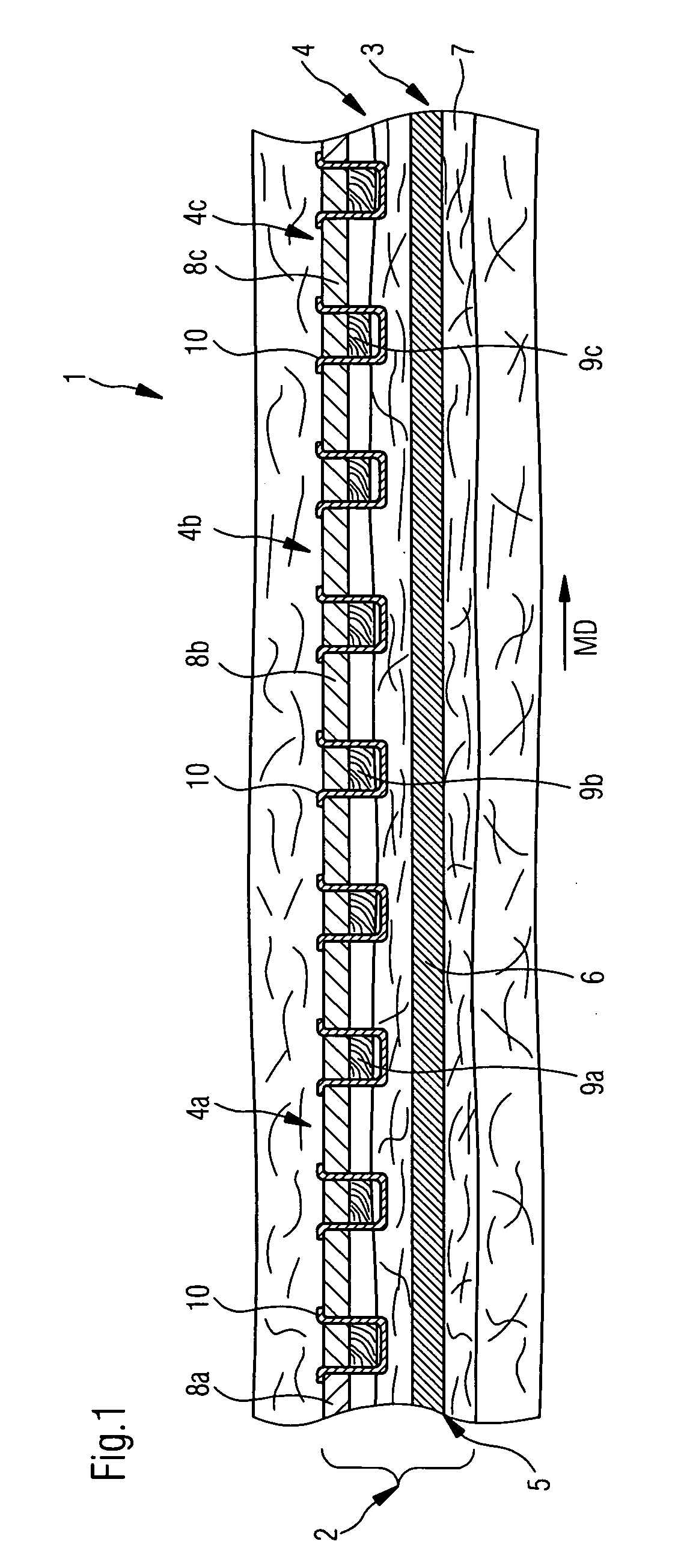
[0091]Referring now to the drawings, and more particularly to FIG. 1, there is shown a longitudinal sectional view of an inventive felt belt 1. It is to be noted that the longitudinal direction of the felt belt 1 is consistent with the machine direction MD.

[0092]The felt belt 1 includes a basic structure 2 which is formed by a longitudinal reinforcement module 3 extending on the width of the felt belt, and including a cross reinforcement module 4, extending on the width of the felt belt.

[0093]The longitudinal reinforcement module 3 includes one laid structure of longitudinal threads on the width of the felt belt 1, which is formed from a group of parallel longitudinal threads 6 (only one such thread is recognizable in FIG. 1) which extend essentially in longitudinal MD direction of the belt 1, and including one carrier layer 6 which is bonded with the laid longitudinal thread structure 5 which extends on the width of the felt belt 1. Said carrier layer 6 is predominantly in the embo...


PUM

PropertyMeasurementUnit
angleaaaaaaaaaa
angleaaaaaaaaaa
angleaaaaaaaaaa

Abstract

The invention relates to a felt belt, especially a press felt for a paper—, cardboard or tissue machine, with a basic structure that is formed by (a) a longitudinal reinforcement module extending on the width and length of the felt belt, including (1) a laid longitudinal thread structure on the width and the length of the felt belt which is formed by at least one longitudinal thread extending essentially in longitudinal direction of the belt, and (2) one carrying layer which is bonded with the laid longitudinal thread structure and extends on the width and the length of the felt belt, as well as (b) one cross reinforcement module which has the same length and width as the felt belt which is located on and bonded with the longitudinal reinforcement module which is formed by a plurality of cross reinforcement module segments, each of which extend on the width of the felt belt, and only on part of the length of the felt belt and which are arranged in tandem in longitudinal direction of the felt belt and which together complete the length of the felt belt, whereby each cross reinforcement segment includes a group of first threads and a group of second threads, whereby the first and the second threads cross each other at thread crossing points and together form a textile surface structure.

Description

BACKGROUND OF THE INVENTION[0001]1. Field of the Invention[0002]The invention relates to a felt belt, especially a press felt for a paper—, cardboard- or tissue machine.[0003]2. Description of the Related Art[0004]Felt belts, especially press felts for paper—, cardboard- or tissue machines normally include a basic structure which provides the dimensional stability of the felt, and which is furnished with one or more fibrous nonwoven layers.[0005]In the past the objective in the development of new press felts was oftentimes to replace the felt belts through a modular composition of individual components and to thereby replace the woven structures.[0006]WO89 / 03300 for example shows felt belts composed of modules. Here, modules are suggested which consist of a laid structure of longitudinal threads which is bonded with one fibrous nonwoven layer, and also of modules which consist of a laid structure of cross threads which is bonded with one fibrous nonwoven layer.[0007]In order to simp...

Claims


Application Information

Patent Timeline
Patent Type & Authority Applications(United States)
IPC IPC(8): D21F3/08B32B37/06
CPCB32B37/04B32B37/22D21F7/083B32B2433/00D21F1/0036B32B38/1816D04B21/165D10B2403/02412Y10S162/90
Inventor KOCKRITZ, UWESCHMITT, MATTHIAS
Owner VOITH PATENT GMBH
Learn More