Method of making a layered composite electrode/electrolyte

Inactive Publication Date: 2005-01-25
RGT UNIV OF CALIFORNIA
View PDF20 Cites 107 Cited by
  • Summary
  • Abstract
  • Description
  • Claims
  • Application Information

AI Technical Summary

Benefits of technology

The present invention addresses this need by providing an electrode fabricated from highly electronically conductive materials such as metals, metal alloys, or electronically conductive ceramics. In this way, the electronic conductivity of the electrode substrate is maximized. The electrode is combined with an electrolyte to form an electrode/electrolyte structure. The electrode/electrolyte structure of the invention may be prepared by a plurality of methods. An unsintered (possibly bisque fired) moderately catalytic electronically-conductive or homogeneous mixed ionic electronic conductive electrode material may be deposited on a layer composed of a sintered or unsintered ionically-conductive electrolyte material prior to being sintered. In one embodiment, a layer of particulate electrode material is deposited on an unsintered (“green”) layer of ele

Problems solved by technology

However, if such compounds were to be used with typical zirconia-based electrolytes, such as YSZ, a deleterious reaction in the temperature range of 1000-1400° C. typically needed to densify zirconia would be expected.
Similar problems may be encountered with sintering highly catalytic electrode materials on densified (fired) zirconia-base electrolytes

Method used


Image

  • Method of making a layered composite electrode/electrolyte
  • Method of making a layered composite electrode/electrolyte
  • Method of making a layered composite electrode/electrolyte

Examples


Example

EXAMPLE

The following example illustrates aspects and features of a specific implementation in accordance with the present invention. It should be understood the following is representative only, and that the invention is not limited by the detail set forth in this example.

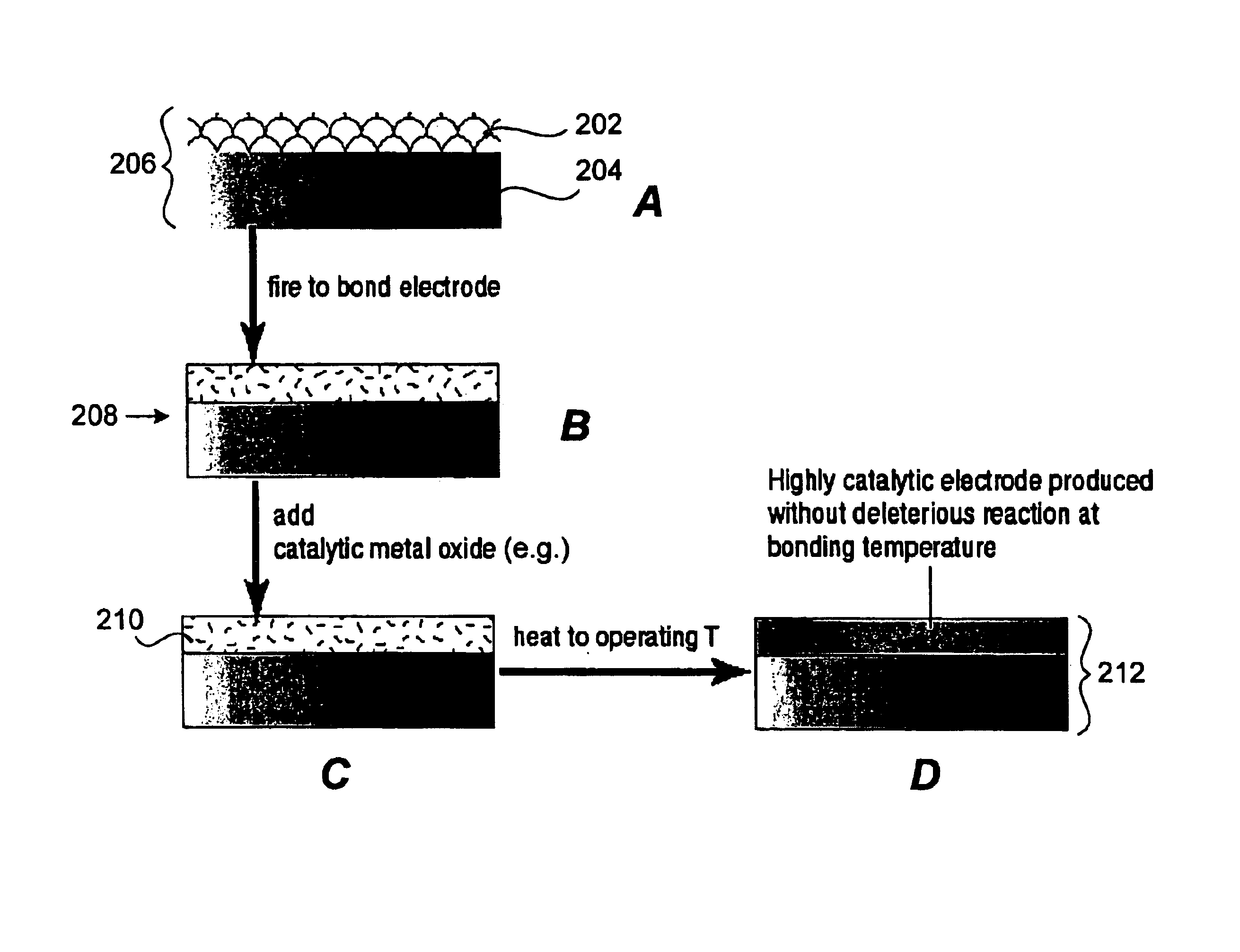
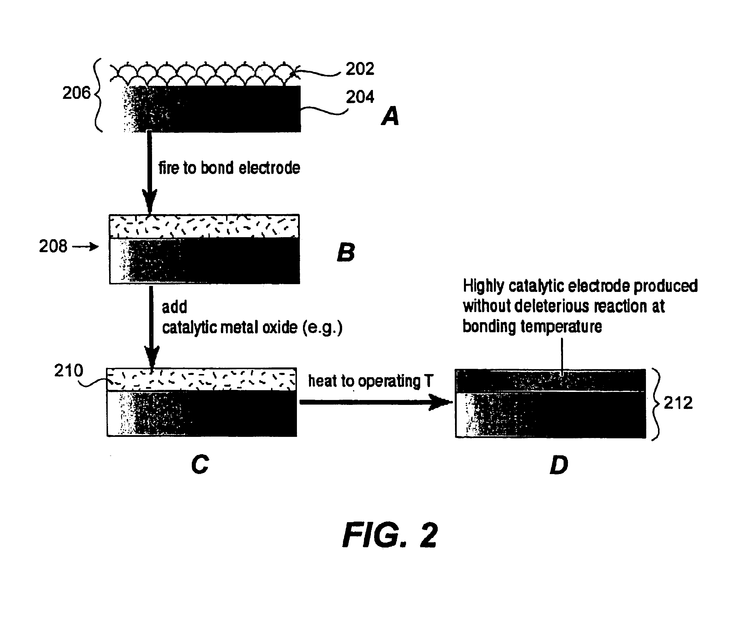
A 1 cm×1 cm Pt electrode (previously fired to 950° C. to bond Pt to electrolyte) was tested on YSZ electrolyte at 900° C. LSM-YSZ was used as the counter electrode. Then a mixture of Co, Sr, Ce, and Ni nitrates dissolved in distilled water were applied to the Pt electrode and allowed to dry under a heat lamp. The sample was again placed in a furnace and heated. Impedance spectra was taken at 900° C. FIG. 3 shows plots of the impedance spectra for the Pt electrode without additives (large arc) and Pt electrode with surface additives (small arc). The example shows the effect of a bare porous metal electrode, Platinum, with and without the addition of metal nitrate salts. The reduction in the size of the impedance arc...


PUM

PropertyMeasurementUnit
Temperatureaaaaaaaaaa
Electrical conductivityaaaaaaaaaa
Electrical conductoraaaaaaaaaa

Abstract

An electrode/electrolyte structure is prepared by a plurality of methods. An unsintered (possibly bisque fired) moderately catalytic electronically-conductive or homogeneous mixed ionic electronic conductive electrode material is deposited on a layer composed of a sintered or unsintered ionically-conductive electrolyte material prior to being sintered. A layer of particulate electrode material is deposited on an unsintered (“green”) layer of electrolyte material and the electrode and electrolyte layers are sintered simultaneously, sometimes referred to as “co-firing,” under conditions suitable to fully densify the electrolyte while the electrode retains porosity. Or, the layer of particulate electrode material is deposited on a previously sintered layer of electrolyte, and then sintered. Subsequently, a catalytic material is added to the electrode structure by infiltration of an electrolcatalyst precursor (e.g., a metal salt such as a transition metal nitrate). This may be followed by low temperature firing to convert the precursor to catalyst. The invention allows for an electrode with high electronic conductivity and sufficient catalytic activity to achieve high power density in an ionic (electrochemical) device such as fuel cells and electrolytic gas separation systems.

Description

BACKGROUND OF THE INVENTIONThe present invention relates generally to the field of electrochemical devices, and more particularly solid state electrochemical devices composed of one or more electrodes in contact with a solid state electrolyte and / or membrane.Solid state electrochemical devices are often implemented as cells including two electrodes, the anode and the cathode, and a dense solid electrolyte / membrane which separates the electrodes. In many implementations, such as in fuel cells and oxygen and syn gas generators, the solid membrane is an electrolyte composed of a material capable of conducting ionic species, such as oxygen ions, sodium ions, or hydrogen ions, yet has a low electronic conductivity. In other implementations, such as gas separation devices, the solid membrane is composed of a mixed ionic electronic conducting material (“MIEC”). In each case, the electrolyte / membrane must be gas-tight to the electrochemical reactants. In all of these devices a lower total i...

Claims


Application Information

Patent Timeline
IPC IPC(8): H01M4/86H01M4/88H01M8/12
CPCH01M4/8626H01M4/8885H01M4/9066H01M8/1246Y10T29/49115H01M2008/1293Y02E60/525Y02E60/50H01M2004/8689Y02P70/50
Inventor VISCO, STEVEN J.JACOBSON, CRAIG P.DEJONGHE, LUTGARD C.
Owner RGT UNIV OF CALIFORNIA
Why Eureka
Try Eureka