Switch connecting structure for timepiece

a technology of electronic timepieces and connecting structures, which is applied in the direction of electric winding, instruments, and horology, can solve the problems of bad contact, so as to prevent and avoid abnormal wear-off or deformation of the contact spring

Inactive Publication Date: 2005-01-25
CITIZEN WATCH CO LTD
View PDF7 Cites 74 Cited by
  • Summary
  • Abstract
  • Description
  • Claims
  • Application Information

AI Technical Summary

Benefits of technology

A switch connecting structure having a plurality of switch springs disposed symmetrically on the outer periphery of the switch regulating plate can allow a movement of a timepiece having the supporting plate provided with a plurality of contact springs to fit in a timepiece case having a different shape, and prevent abnormal wear-off or deformation of the contact spring.
A switch connecting structure provided with a plurality of hook portions hooking onto the movement of the timepiece and disposed on the outer periphery of the switch regulating plate makes it possible to hook the switch regulating plate onto the movement of the timepiece and fix the position of the plate with respect to the movement, thereby allowing the plate to be handled together with the movement.
When the switch spring of the switch regulating plate extends substantially in parallel to a inside wall of a body of said timepiece case and has a round portion where it contacts said contact spring, the pressing force of the push button is applied in the substantially vertical direction to the tip of the switch regulating plate, and the force of the switch regulating plate is applied on the supporting plate in the substantially central direction of the movement. As a result, the tip portion of the push button can be brought into a line contact with the contact spring of the supporting plate, and the switch spring of the switch regulating plate can be brought into a line contact at the round portion with the contact portion of the contact spring of the supporting plate, thereby avoiding abnormal wear-off or deformation of the contact spring.
When the switch spring of the switch regulating plate extends substantially in parallel to a inside wall of a body of the timepiece case and has a corner extending substantially in parallel to the contact spring and provided at a position where it contacts the contact spring, the pressing force of the push button is applied in the substantially vertical direction to the tip portion of the switch regulating plate, and the force of the switch regulating plate is applied on the supporting plate in the substantially central direction of the movement. As a result, the tip portion of the push button can be brought into a line contact with the contact spring of the supporting plate, and the switch spring of the switch regulating plate can be brought into a line contact with the contact spring of the supporting plate at the corner portion extending in parallel, thereby avoiding abnormal wear-off or deformation of the contact spring.

Problems solved by technology

Consequently, depression of the push button 4 results in abnormal wear-off or deformation of the contact spring 3a of the supporting plate.
Therefore, repeated use of the push button 4 causes an unstable contact between the contact portion 3b of the supporting plate 3 and the switch contact portion 2a of the circuit board 2, possibly leading to a bad contact, abnormal wear-off or deformation.
The push button 4 may be deformed during processing of the button, and extra material is required, leading to an increase in manufacturing cost.

Method used


Image

  • Switch connecting structure for timepiece
  • Switch connecting structure for timepiece
  • Switch connecting structure for timepiece

Examples


first embodiment

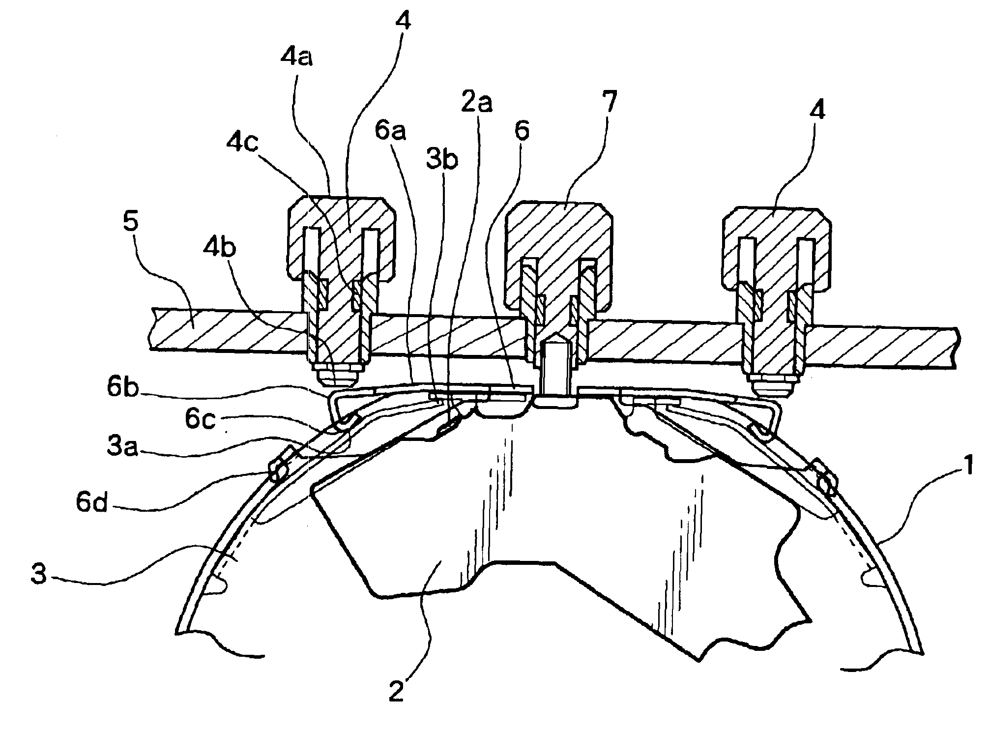
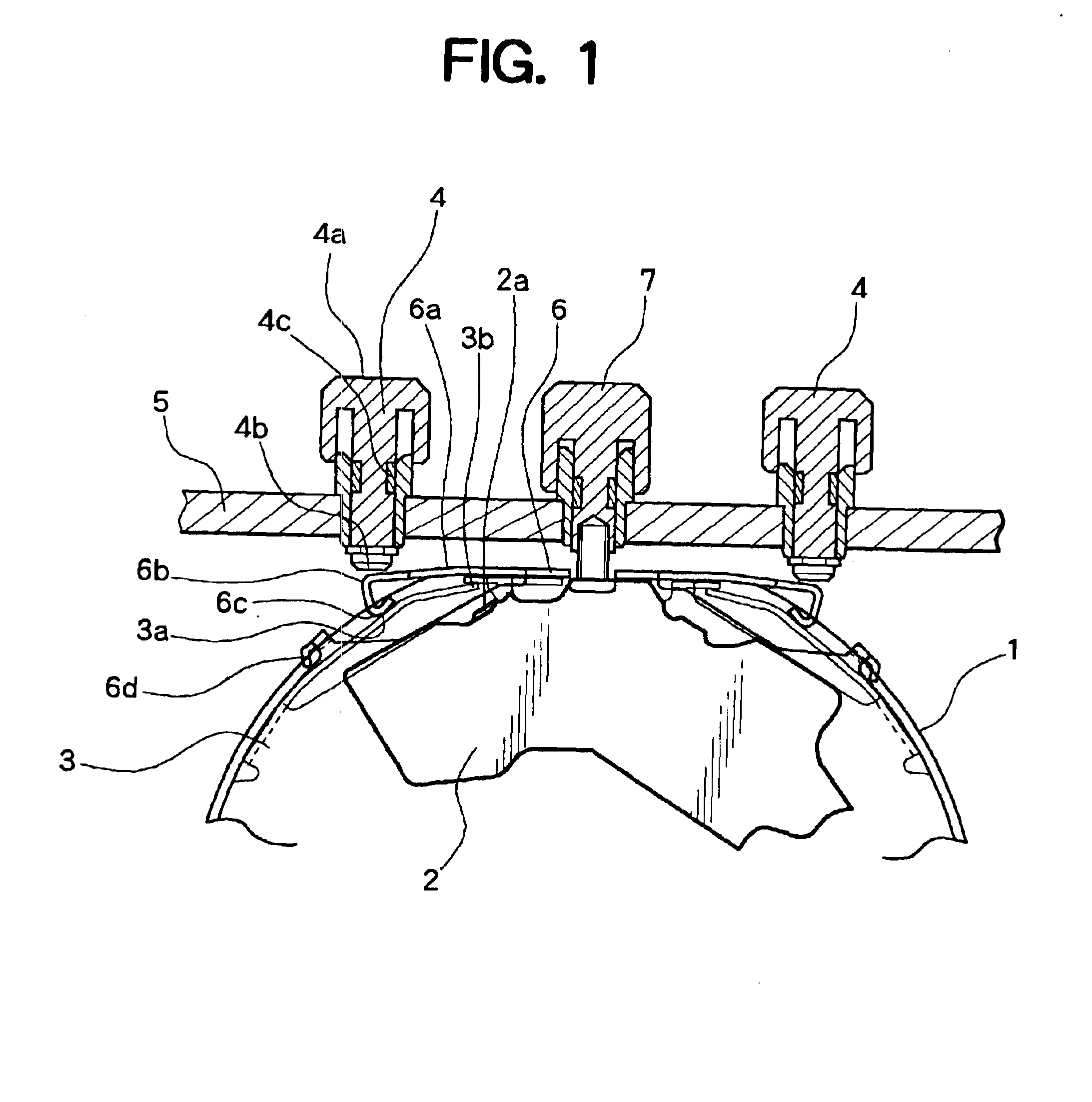
A switch connecting structure according to the present invention will be described with reference to the drawings. FIGS. 1-4 illustrate a switch connecting structure according to the present invention in which a circular movement is placed in a square watch case. FIG. 1 is a plan view illustrating an important part. A push button and a case are shown in cross section. FIG. 2 is a plan view of a supporting plate. FIG. 3 is a plan view of a switch regulating plate. FIG. 4 is a side view illustrating how a movement assembly is disposed. The components corresponding to those in the related art (illustrated in FIG. 10) are labeled with the corresponding numerals and characters.

A circular movement 1 is capped by a supporting plate 3 illustrated in FIG. 2. A contact spring 3a is suspended from the body of the supporting plate 3 on the outer periphery of the plate 3, extending around the movement and having a contact portion 3b at the tip. The tip contact portion 3b abuts a restricting port...


PUM


Abstract

An inexpensive switch connecting structure is provided capable of avoiding abnormal wear-off or deformation of a contact spring of a supporting plate even if a movement in a basic shape is placed in a timepiece case having a shape different from the movement and a push button is repeatedly used. The switch connecting structure includes a supporting plate attached to cap a movement of a timepiece and provided with a contact spring having a contact portion at a tip brought into contact with a switch contact portion of a circuit board, and a switch regulating plate provided with a switch spring on an outer periphery corresponding to said contact spring and covering at least part of said supporting plate, wherein said switch spring is flexed by operation of an externally operated component attached to a timepiece case, thereby bringing the contact portion of the contact spring of said supporting plate into contact with the switch contact portion of said circuit board. The switch spring of the switch regulating plate acts as an intermediary to properly convey the pressing force from the externally operated component such as a push button attached to the timepiece case having a different shape from the basic shape of the movement.

Description

BACKGROUND OF THE INVENTION1. Field of the InventionThe present invention relates to a switch connecting structure of a multifunctional electronic timepiece having an externally operated component.2. Description of the Prior ArtIn recent years, multifunctional electronic timepieces, such as watches provided with chronograph function and the like, have been commercially available in the market. Generally, in such a multifunctional electronic watch, a supporting plate is attached to substantially cap a planar portion of a basic circular movement, and is placed in a body of a watch case having substantially the same shape as the movement. In the switch connecting structure, depression of a push button, i.e. an externally operated component disposed at a predetermined position of the body of the case, causes a contact spring provided on the supporting plate to contact a switch contact on a circuit board, thereby electrically connecting to elements of electronic components provided in th...

Claims


Application Information

Patent Timeline
Patent Type & Authority Patents(United States)
IPC IPC(8): G04C3/00
CPCG04C3/001
Inventor HASUMI, TAKAYUKIYAMADA, SHINICHISHIMODA, KENJI
Owner CITIZEN WATCH CO LTD
Why Eureka
Try Eureka