Flashing

a flashing and flashing technology, applied in the field of flashing, can solve the problems of not being able to provide a flashing, risk of too much being cut, and being to low

Inactive Publication Date: 2005-02-01
VKR HLDG AS
View PDF10 Cites 34 Cited by
  • Summary
  • Abstract
  • Description
  • Claims
  • Application Information

AI Technical Summary

Benefits of technology

In view of the above it is an object of the invention to provide a flashing for weather proof sealing of the transition between a roof covering and a constructional element rising from a roof surface, such as a curb of a skylight of a so-called curb and lens construction, said flashing comprising a sheet material flashing profile strip divided by a bend into a first profile portion for abutment against the constructional element and a second profile portion for extending along the roof surface, said bend extending in a longitudi

Problems solved by technology

In such a case it has hitherto not been possible to provide a flashing that will fit the curb in all cases, because the selection of timber is more or less arbitrary.
This in turn entails the risk of to much being cut of, the flashing being as a con

Method used


Image

  • Flashing
  • Flashing
  • Flashing

Examples


Embodiment Construction

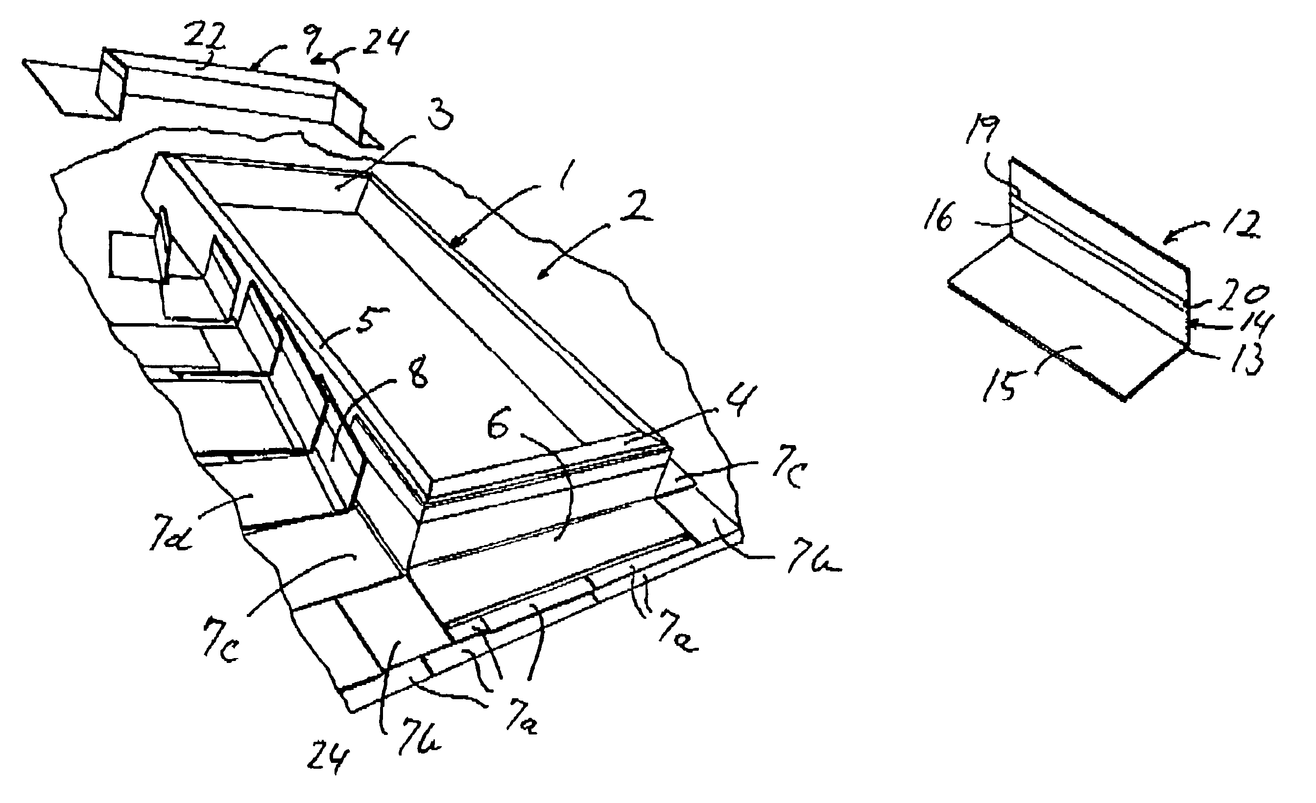
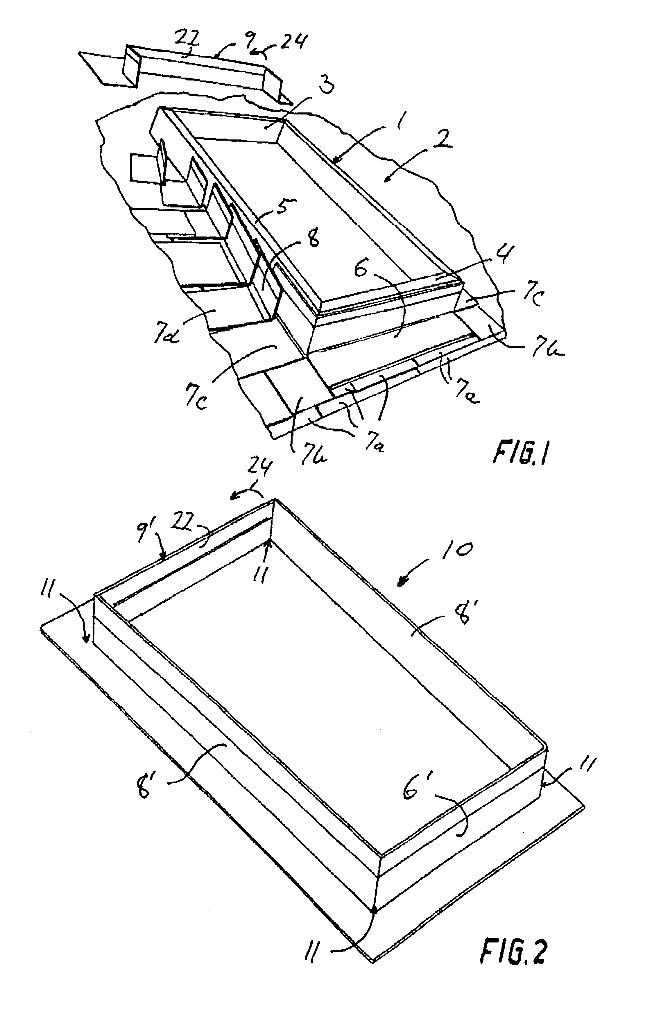
FIG. 1 shows a constructional element in the shape of a curb 1 for a skylight, the curb rising from the surface 2 of an inclined roof. The curb 1 comprises a curb top part 3, a curb bottom part 4 and curb side parts 5. The curb 1 is build on site from timber of dimensions 2″×6″ (inches).

FIG. 1 further illustrates installation of a flashing and a roof covering in the shape of shingles. A flashing bottom part 6 extending along the curb bottom part 4 and lower parts of the curb side parts 5 has been mounted overlaying lower shingles 7a. Intermediate shingles 7b and 7c have been mounted overlaying the ends of the flashing bottom part 6. A first piece 8 of flashing side part is ready for mounting overlapping the flashing bottom part 6 and the upper intermediate shingle 7c following which a further intermediate shingle 7d will be mounted overlaying the first piece 8 of flashing side part. This procedure is continued as known per se until the curb side parts 5 are provided with flashing. F...


PUM


Abstract

A flashing for weather proof sealing of the transition between a roof covering and a constructional element rising from a roof surface, such as a curb of a skylight, comprises an elongated flashing profile strip with a first profile portion for abutment against the constructional element and a second profile portion for extending along the roof surface. The first profile portion has a defined width transverse to a longitudinal direction of the profile strip, and the first profile portion comprises a separation line running in the longitudinal direction of the profile strip. The separation line facilitates separation of an outer part of the first profile portion.

Description

BACKGROUND OF THE INVENTIONThe present invention relates to a flashing for weather proof sealing of the transition between a roof covering and a constructional element rising from a root surface, such as a curb of a skylight, said flashing comprising an elongated flashing profile strip with a first profile portion for abutment against the constructional element and a second profile portion for extending along the roof surface, said first profile portion having a defined width transverse to a longitudinal direction of the profile strip.Flashings are commonly used e.g. to provide a weather proof sealing between a roof surface and the frame or curb of a roof window or skylight.Roof windows are delivered by a manufacture as a complete construction including a frame for mounting on the construction of the roof. In such a case it is possible for the manufacture to deliver also a flashing that will fit the frame.However skylights are often delivered as a sash with glazing but without a fra...

Claims


Application Information

Patent Timeline
IPC IPC(8): E04D13/14E04D13/03E04D13/147
CPCE04D13/1475E04D13/0315
Inventor FAURHOLDT, JESPER HENRIKJENSEN, JAN FAHLENNISSEN-SCHMIDT, LARS J.O SLASHED.RNLAWTON, JR., JOHN E.QUARLES, WAYNE
Owner VKR HLDG AS
Why Eureka
Try Eureka