Method for controlling quality and condition on the basis of thermal imaging

a technology of thermal imaging and quality control, applied in the direction of optical radiation measurement, instruments, material flaw investigation, etc., can solve the problems of easy disassembly and use of thermal image information, and easy disassembly of transient phenomena which may only occur recurrently, so as to achieve efficient elimination of random noise and low intensity

Inactive Publication Date: 2005-02-01
METSO AUTOMATION OY
View PDF9 Cites 37 Cited by
  • Summary
  • Abstract
  • Description
  • Claims
  • Application Information

AI Technical Summary

Benefits of technology

By means of the invention, it is also possible to detect transient phenomena which occur only momentarily in the machine direction and which have been, until now, impossible to determine by methods of prior art. Another very significant advantage of the invention is that the cause of failures in the process can now be identified by means of the invention in an easier and more reliable way than in prior art.
is that the cause of failures in the process can now be identified by means of the invention in an easier and more reliable way than in prior art.
The essential basic idea of the invention is that a two-dimensional thermal image, i.e. a thermal chart, of a measurable moving object is recorded by a thermal camera in a continuous manner so that said continuous thermal chart is synchronized in time with the movement of the object to be measured.
Consequently, by means of time-resolved thermal imaging, a location-resolved thermal chart, substantially continuous in the machine direction, is formed of the surface of the object to be imaged. In this thermal chart, for example areas corresponding to different points on the surface of the fibre web are shown in a location-resolved manner both in the cross-machine direction and in the machine direction.
Now, the synchronization of the two-dimensional thermal chart with the movement of the object will further make it possible to detect from the thermal chart, in an efficient and, if necessary, automatic way, recurrent and transient phenomena in the machine direction, and furthermore, the causes of these recurrent phenomena can be identified on the basis of the periodicity of the phenomena.
If the object to be imaged is, for example, a moving fibre web, the cause of a defect recurring at regular intervals in the web can be identified as a roll rotating at a known peripheral speed in relation to the web, wherein a damaged or soiled point on the surface of the roll causes a defect in the passing web, recurring at intervals corresponding to the peripheral length of said roll.

Problems solved by technology

However, the above-presented prior art methods utilizing a thermal camera involve the problem that the information contained in the thermal images is primarily analyzed by the user viewing the images.
For this reason, some of the information contained in the thermal images may also easily remain unutilized.
Furthermore, the solutions of prior art involve the problem that transient phenomena which may also occur only recurrently are easily disregarded by the user.
In particular, phenomena which are very low in intensity and occur only recurrently in thermograms are very difficult to be detected by the human eye.
The first-mentioned method has the disadvantage of high equipment costs caused by the cameras, whereas the latter method has the disadvantage of slowness and poor repeatability of the manual measurements.

Method used


Image

  • Method for controlling quality and condition on the basis of thermal imaging
  • Method for controlling quality and condition on the basis of thermal imaging
  • Method for controlling quality and condition on the basis of thermal imaging

Examples


Embodiment Construction

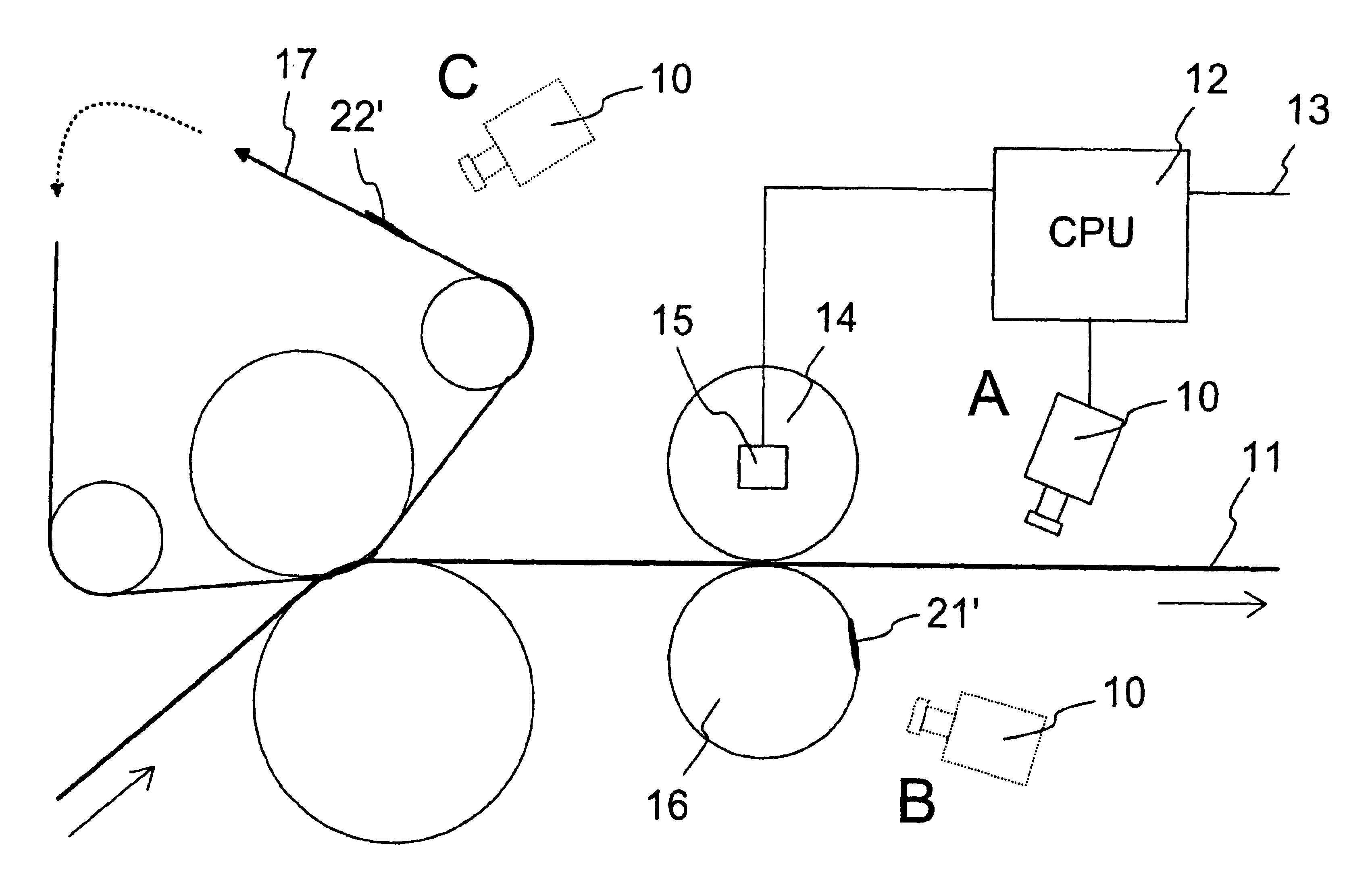
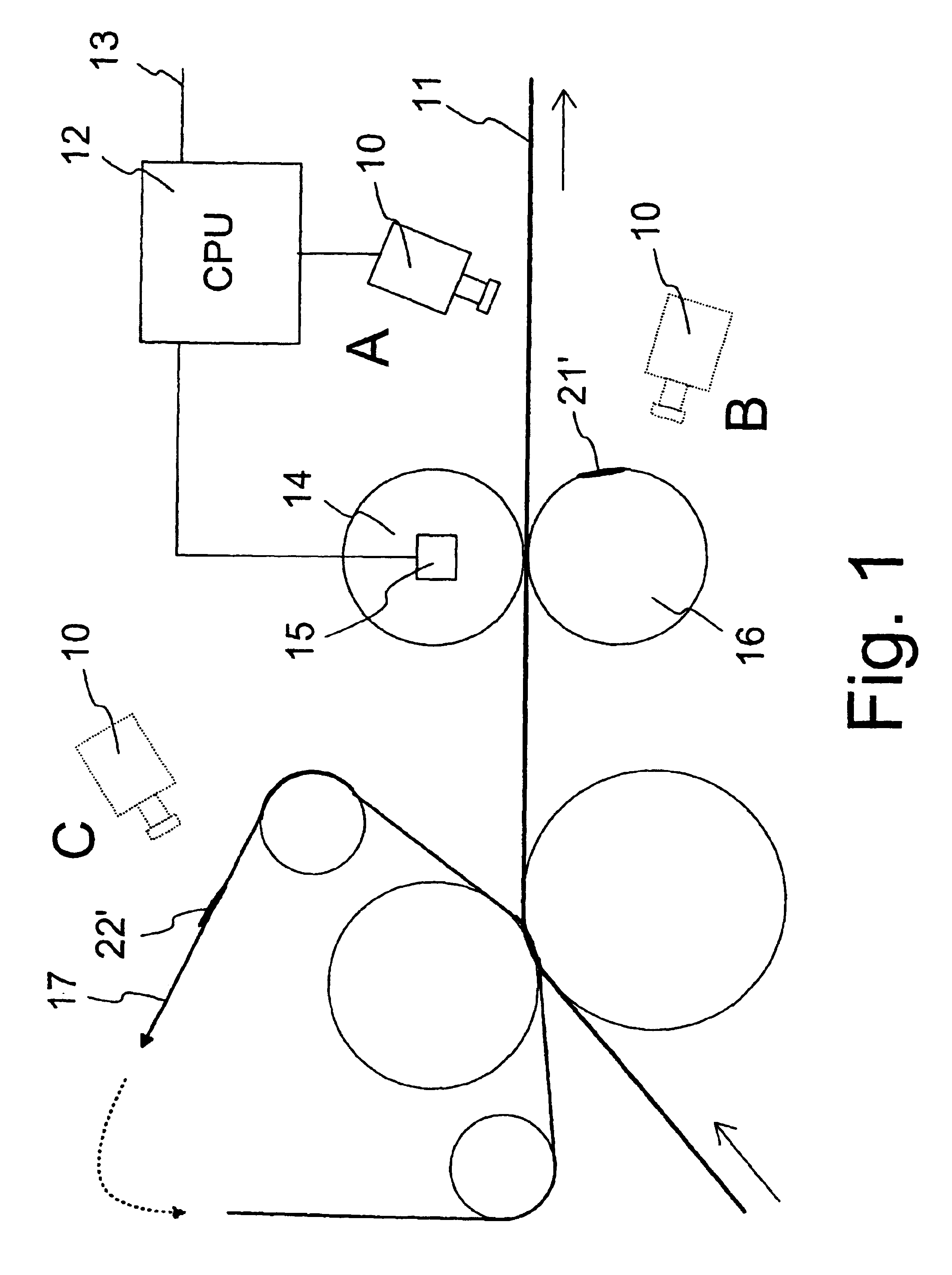
FIG. 1 shows, in principle, some possible embodiments of the invention which correspond to different positions A, B and C of a thermal camera indicated in FIG. 1.

A thermal camera 10 located in the position A is arranged to image a moving web 11 as the object of measurement, to form a continuous thermal chart of the web 11 in accordance with the invention. The web 11 can be a fibre web present in various forms in paper or board manufacture, and depending on the location of the measurement, the web can also be supported at the imaging point by a wire, a roll or another means on the side opposite to the imaging direction.

The thermal camera 10 can be a conventional infrared camera which is based on the use of a single detector element and in which a rotating mirror or a corresponding arrangement is used to direct infrared radiation from the object to the infrared-sensitive detector element by the scanning principle. In other words, the measuring range detected by the detector element is...


PUM

PropertyMeasurementUnit
infrared wavelength rangeaaaaaaaaaa
speedaaaaaaaaaa
operating wavelength rangeaaaaaaaaaa

Abstract

A method in the process of manufacturing and / or finishing a fiber web (11), in which method the Continuous and moving web (11), and / or a moving device (16, 17) related to the processing of the web (11), is monitored by one or more thermal cameras (10) of the infrared range or a corresponding detector / detectors for the purpose of controlling the quality or condition. A substantially continuous two-dimensional thermal image or continuous thermal chart (20) of an object (11, 16, 17) being monitored and in a propagating and / or rotating movement is formed by said detector / detectors in a time-resolved manner and in synchronization with the movement of the object (11, 16, 17) in the direction of the movement. To determine the properties of the object (11, 16, 17) and / or to detect defects in the object from the continuous thermal chart (20), local deviations and / or discontinuities (21, 22) in the temperature, particularly in the direction of movement are detected, and the cause of said deviations and / or discontinuities (21, 22) is identified on the basis of the periodicity of said phenomena in the direction of movement.

Description

FIELD OF THE INVENTIONThe invention relates to a method for controlling quality and condition on the basis of thermal imaging, to be used in connection with processes of manufacturing and / or finishing a continuous fibre web.BACKGROUND OF THE INVENTION AND PRIOR ARTWith improved technology and usability of thermal cameras, they are being increasingly used in various industrial condition and quality control applications. Conventionally, thermal imaging has been used for monitoring the condition of various apparatus components. Typical uses have included, for example, the monitoring of the condition of various engines and bearings at intervals. By means of thermal imaging, defects in components can be detected in a contactless manner, for example as an increase in the surface temperatures of the components.In paper industry, thermal imaging has also been applied to measure properties of the fibre web to be manufactured and / or processed, various rolls, as well as reels formed of the web...

Claims


Application Information

Patent Timeline
Patent Type & Authority Patents(United States)
IPC IPC(8): D21G9/00G01N25/72G01N33/34G01N21/88G01N21/892
CPCD21G9/0027D21G9/0036G01N33/346G01N25/72G01N21/8922
Inventor KOMULAINEN, ANTTIJUPPI, KARIAIMONEN, PERTTI
Owner METSO AUTOMATION OY
Why Eureka
Try Eureka