Bed frame center beam locking mechanism

a technology of center beam and locking mechanism, which is applied in the field of bed frames, can solve the problems of extension bars being sent to customers, too long to be used with a small bed frame, inventory, labeling and identification problems, etc., and achieve the effect of correctly installed and easy and quick connection

Inactive Publication Date: 2005-02-08
FINGER LAKES INTPROP
View PDF8 Cites 28 Cited by
  • Summary
  • Abstract
  • Description
  • Claims
  • Application Information

AI Technical Summary

Benefits of technology

A lever arm is pivotally affixed to the frame and is also movably affixed to the ends of the pawls. By rotating the lever arm, the pawls are caused to move between their locked and unlocked positions and an overcenter, toggle mechanism causes the pawls to become locked in their locked positions so as to firmly affix the center beam to the cross bars in the assembly of the bed frame. Accordingly, by use of the present mechanism, the center beam can be affixed securely to the cross bars of the bed frame without the need for any screws of other devices that would require hand tools by the assembler. In order to assure the proper alignment of the center beam, there are also a number of bent tabs that extend downwardly from the locking mechanism frame and which enter prealigned holes in the cross bar to be assured that the position of the center beam is proper with respect to the cross bars.
In the case of a king size or California king size bed frame, the center beam locking mechanism is used to affix the center beam to an extension bar, however, the extension bar of the present invention is designed to be a universal extension bar and the same extension bar is used for both the king size bed frame as well as the California king size bed frame. Thus, as in the prior art, an extension bar is used to join the cross bar members to complete the cross bar in assembling the bed frame, however with the universal extension, there are different sets of standoff rivets and keyhole slots so that the assembler can select the appropriate set of standoff rivets and keyhole slots applicable for the particular bed size that is desired.
In order to aid the assembler in selecting the correct set or sets of keyhole slots to interfit with the appropriate standoff rivets, an extension cap, preferably comprised of a plastic material, is provided that, in the preferred embodiment, can simply be snapped on to the universal extension bar and which provides indicia, either in written form or by appropriate color, or both, to clearly indicate to the assembler what standoff rivets interfit with the appropriate sets of keyhole slots to make up either a king size bed frame or a California king size bed frame. By the use of the plastic extension cap, therefore, the assembler can easily and quickly make the correct connections between the mating standoff rivets and the keyhole slots to assemble the bed frame for either the king size or the California king size bed frames and be assured that the extension bar and the center beam is correctly installed.
In the same embodiment, there are bent tabs that extend downwardly from the center beam locking mechanism and which interfit with appropriate holes formed in the universal locking bar, and again, there is indicia provided on an extension cap affixed to the universal extension bar to clearly indicate to the assembler, which are the appropriate and correct holes or sets of holes to be interfitted with the set of tabs to properly align the center beam for those bed frame sizes, that is, for the king or California king size bed frame. Thus, with the extension cap, not only can the assembler correctly determine the proper sets of standoff rivets to interfit with a set of keyhole slots, but the alignment and positioning of the center beam is also assured by the indicia on the extension cap clearly indicating to the assembler the correct holes on the universal extension bar into which the downwardly extending tabs are to be inserted.

Problems solved by technology

Otherwise, if the cross bars were deliberately made to be of sufficient lengths for a king or California king size bed, they would be too long to be used with a small bed frame as they would extend outwardly beyond the normal width of those bed frames, that is, the cross bars would need to extend longer than the width of small bed frame.
Accordingly the differing length extension bars for the king and California king size bed frames require the supplier to maintain an inventory of each of the extension bars to be shipped depending on the particular frame size, thereby creating an inventory, labeling and identification problem and also raising the possibility that the wrong extension bar can be sent to the customer and incur the annoyance of that customer and the need to spend time to correct the problem.

Method used


Image

  • Bed frame center beam locking mechanism
  • Bed frame center beam locking mechanism
  • Bed frame center beam locking mechanism

Examples


Embodiment Construction

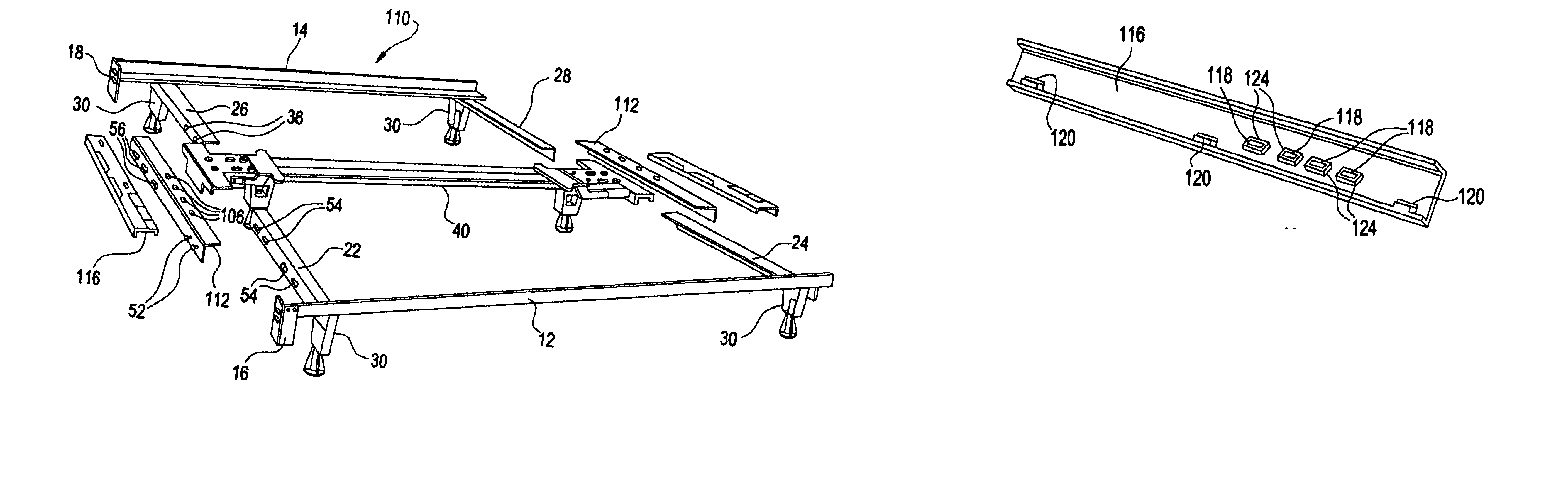
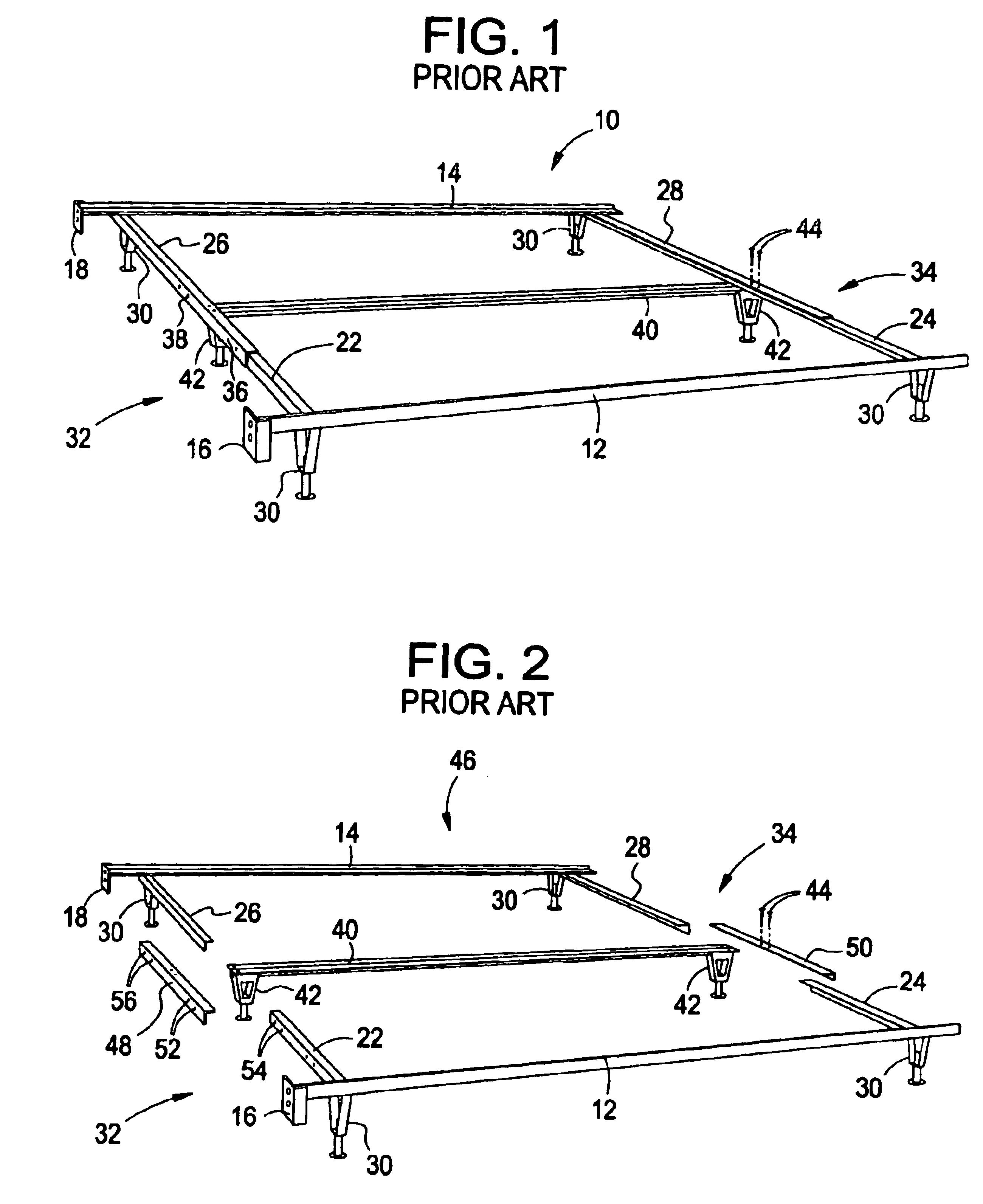
Referring now to FIG. 1, there is shown a perspective view of a conventional bed frame 10 and is typical of a bed frame that is a queen size or smaller. In the Figure, there are a pair of side rails 12, 14 that are normally L-shaped steel members and at one end thereof, there are normally located brackets 16, 18 to aid in the attachment of a headboard to the side rails 12, 14. To make up the bed frame 10, there are also cross bar members 22, 24, 26 and 28 that extend outwardly from side rails 12, 14 at about a right angle. As explained, for the convenience of handling and transportation of the components of a bed frame 10, the cross bar members 22, 24, 2628 are pivotally mounted to the side rails 12, 14, that is, cross bar members 22 and 24 are pivotally mounted to the ends of side rail 12 while cross bar members 26 and 28 are pivotally affixed to the ends of side rail 14. As an example, therefore, during shipment, the cross bar members 22 and 24 are positioned 90 degrees from the o...


PUM


Abstract

A locking mechanism for securing a center beam of a bed frame to the cross bars that enable the assembler to complete the assembly of the bed frame completely without the need for hand tools or securing implements to aid in the assembly. With a queen size bed frame or smaller, the cross bar members are joined together in overlapping manner to form cross bars and the center beam is secured to the cross bars by use of the present locking mechanism. In the case of a king size or a California king size bed frame, a universal extension bar is provided that can be used to join the cross bar members of either size bed frame and a extension cap is also provided that is affixed to the universal extension bar having indicia that instructs the assembler in the proper assembly of the particular bed frame.

Description

BACKGROUND OF THE INVENTIONThe present invention relates to bed frames, and, more particularly, to a mechanism that facilitates the interconnection of a center beam in setting up a bed frame.In general, bed frames are comprised of a pair of side rails and a plurality of cross bars that span between the side rails in order to assemble and complete the bed frame structure. The bed frame, once assembled is adapted to support a box spring and a mattress to make up the bed itself. Normally, therefore, the bed frame assembly is shipped and delivered unassembled for convenience and general transportation and the two side rails comprise L-shaped steel members. The cross bars are formed of cross bar members that are pivotally affixed at or near each end of the side rails. In the assembly of the bed frame at the location of the customer, therefore, the cross bar members are interfitted with and parallel to the side rails for ease of shipment and the cross bar members are pivoted about 90 degr...

Claims


Application Information

Patent Timeline
Patent Type & Authority Patents(United States)
IPC IPC(8): A47C19/04A47C19/00A47C19/02
CPCA47C19/005A47C19/04A47C19/025A47C19/021
Inventor POLEVOY, RICHARD S.RYAN, HOWARD SCOTTCARLSON, PAUL ERIC
Owner FINGER LAKES INTPROP
Why Eureka
Try Eureka