Spring-loaded oil overflow valve for diaphragm compressors

Inactive Publication Date: 2005-02-08
KLEIBRINK HORST
View PDF2 Cites 19 Cited by
  • Summary
  • Abstract
  • Description
  • Claims
  • Application Information

AI Technical Summary

Benefits of technology

The object of the present invention is to provide a spring-loaded overflow valve without the requirement of an additional valve control whereby the excessively long open times of the oil overflow valve with the various operating conditions of the oil space are avoided.
The object is achieved by means of a flow interrupting edge formed at the junction of the seat and a restriction piece coupled to the overflow valve outlet. The edge sharply reduces the output force of the valve spindle, and with that the effective downward spring force, as the dominant force component, leads to the desired faster closing times of the valve.

Problems solved by technology

Since this cannot be technically realized, always an injected amount of oil is used which is larger than the leakage.
This in turn has the result that with each stroke of the compressor piston somewhat too much oil is contained in the oil space, which then at the forward dead point of the diaphragm(that is, engaging the cover), leads to an uncontrollable increase in oil pressure.
The latter leads to undesirable increases in the opening time of the oil overflow valve such that more oil is discharged than introduced by the compensation pump.
This has the result that after many pumping strokes the diaphragm is no longer driven to its forward dead point.
Consequently, not all of the compressed gas is discharged which is accompanied by a rapid decrease in the suction power.

Method used


Image

  • Spring-loaded oil overflow valve for diaphragm compressors
  • Spring-loaded oil overflow valve for diaphragm compressors
  • Spring-loaded oil overflow valve for diaphragm compressors

Examples


Embodiment Construction

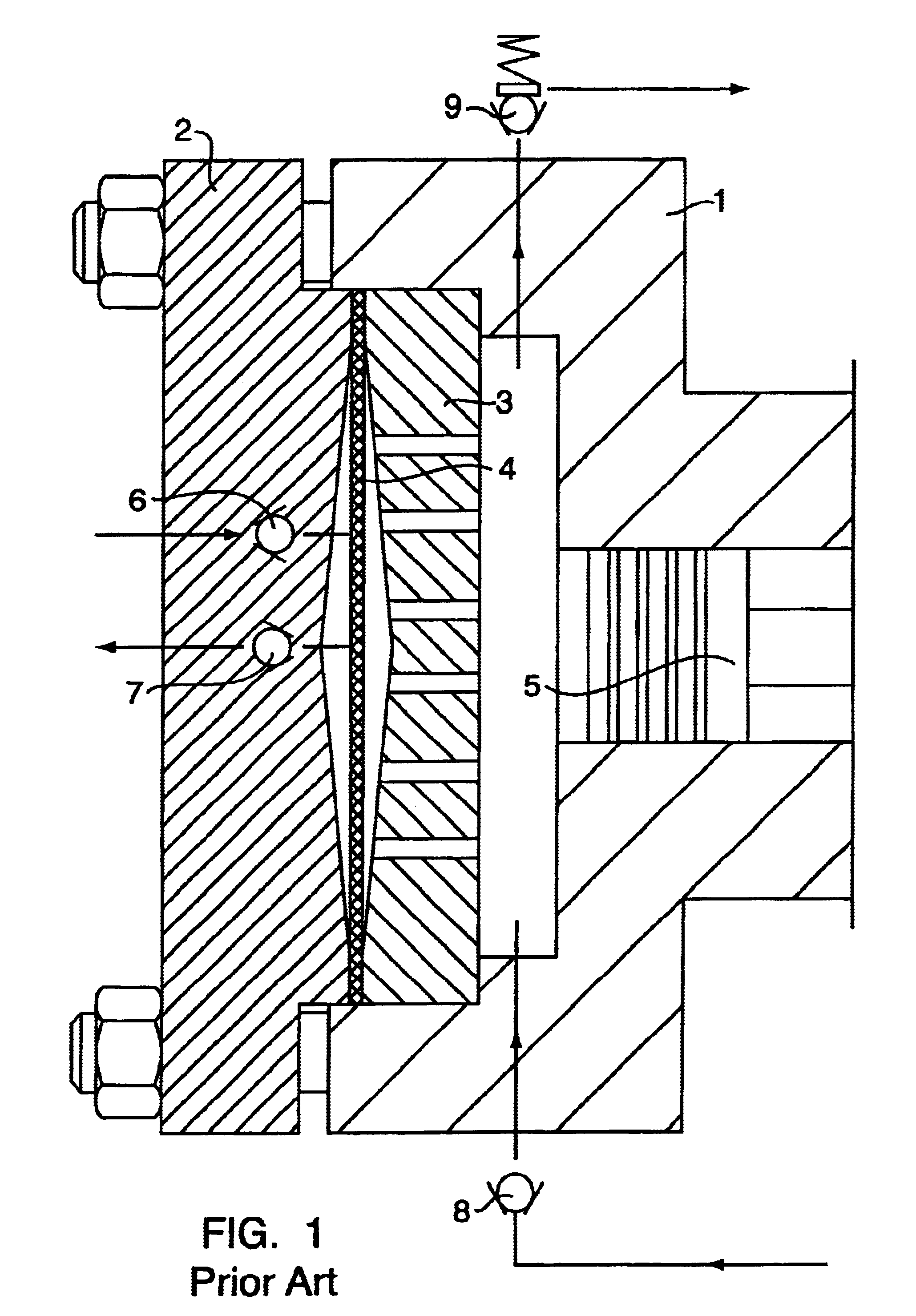
The principal components of a diaphragm compressor according to FIG. 1 include a flange with a cylinder (1), a cover (2), an aperture plate (3), a diaphragm (4), a piston (5), a suction valve (6), a pressure valve (7), a check valve (8), and an overflow valve (9). The volume designated as the oil space extends between the piston (5) and the diaphragm (4). The volume designated as the gas space extends from the diaphragm (4) to the cover (2). The diaphragm displacement volume is matched with the piston displacement volume (surface area×stroke), so that the effectiveness of a piston compressor exists. The diaphragm operates in volume synchronization with the piston, drawing in the gas through the suction valve 6, compressing the gas and expelling the gas through the pressure valve 7.

The leakage of oil at the piston (5) must be compensated for by an external pump. For this, a small piston pump driven by an eccentric is used, which pump with each stroke injects a small amount of oil int...


PUM


Abstract

A diaphragm head with a high energy content of the oil space (pressure×volume) has a strong negative influence on the corresponding behavior of the oil overflow valve. The reaction of the valve leads to an undesirable increase in the opening time by which more oil is discharged than oil introduced by means of a compensation pump. This has the result that after multiple strokes the diaphragm is not driven to its dead position. With this, all of the compressed gas is not expelled which is accompanied by a rapid decrease of the suction capacity.The solution to this problem according to the present invention is achieved by means of a flow-interrupting edge formed at the junction of the valve seat and a restriction piece at the outlet side by which the operating forces of the valve spindle are sharply reduced. With this the effective closing force of the spring, as the dominant force component, leads to the desired fast closing time to the valve.

Description

CROSS REFERENCE TO RELATED APPLICATIONApplicant hereby claims foreign priority under 35 U.S.C. §119 from German Application No. 102 21 077.2 filed 11 May 2002, the disclosure of which is herein incorporated by reference.BACKGROUND OF THE INVENTIONThe invention relates to a spring-loaded oil overflow valve for diaphragm compressors.Diaphragm compressors operate similarly to normal piston compressors, but with a separating diaphragm between the gas side and the oil side. The oil side is formed by the usual piston-cylinder unit, whose working and dead volumes are filled with oil. On the gas side are gas suction and pressure valves. The volume displaced by the oscillating movement of the piston is transmitted to the diaphragm, which then on its gas side causes the intake, compression and exhaust of the gases. Since the oil pressure during the entire reciprocating movement corresponds to the course of the suction and compression pressure on the gas side, one can here also talk in terms o...

Claims


Application Information

Patent Timeline
IPC IPC(8): F04B43/06F04B43/067F16K17/04F16K15/04F16K15/02
CPCF04B43/067F16K17/0406F16K15/044Y10T137/7928
Inventor KLEIBRINK, HORST
Owner KLEIBRINK HORST
Why Eureka
Try Eureka