Y-body Christmas tree for use with coil tubing

a technology of coil tubing and christmas tree, which is applied in the field of y-body christmas tree, can solve the problems of inoperable shut-off valve, damaged valve, and inoperable shut-off valve,

Inactive Publication Date: 2005-02-08
STREAM FLO INDS
View PDF5 Cites 60 Cited by
  • Summary
  • Abstract
  • Description
  • Claims
  • Application Information

AI Technical Summary

Benefits of technology

The Y-body Christmas tree controls the passage and pressure of well flow. This is generally achieved with at least one shut-off valve and provides a means to shut-off the well flow in the vertical bore. Containing well flow below the shut off valve prevents it from accessing the flow bore outlets. This valve essentially shuts off the well.

Problems solved by technology

Several problems can arise with this approach.
To shut off the well in case of an emergency, the shut off valve may become inoperative because of interference with the coil tubing.
The coil tubing may have to be severed by the shut off valve in order to control the well, and by doing this, the valves may be damaged.
In either case, the shut off valves can become problematic or inoperative, and well control is given up.
This is a time-consuming approach to run in and install the coil tubing parallel to, and at the same time as, the tubing string.
An example of this type of spool device is an RH-Y Capillary Spool available from Wellhead Control Products, Inc., Texas, U.S.A. This spool adds height to the wellhead, requires relocation of flowlines for existing wells, and creates significant safety issues as it becomes more difficult to work on the wellhead.

Method used


Image

  • Y-body Christmas tree for use with coil tubing
  • Y-body Christmas tree for use with coil tubing
  • Y-body Christmas tree for use with coil tubing

Examples


Embodiment Construction

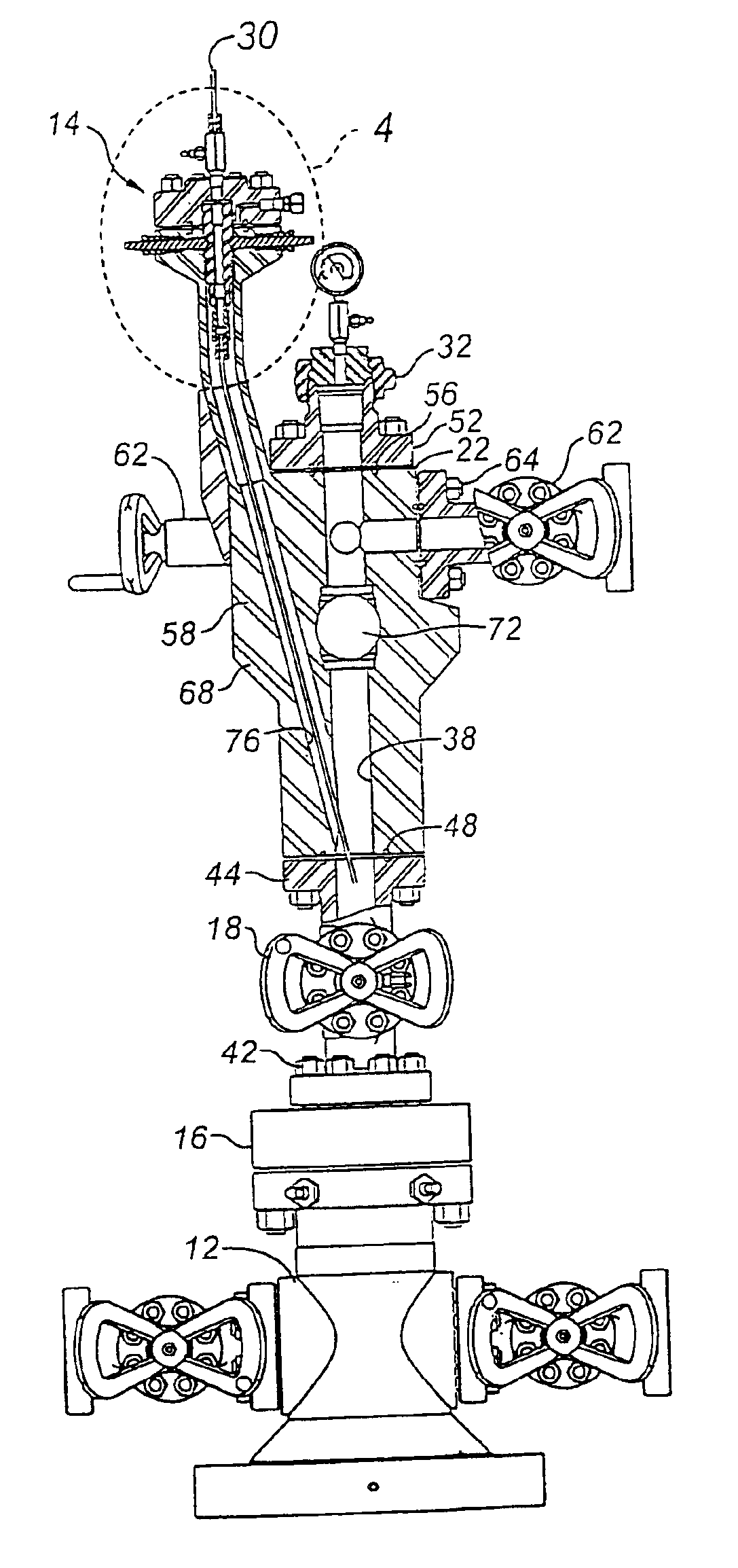
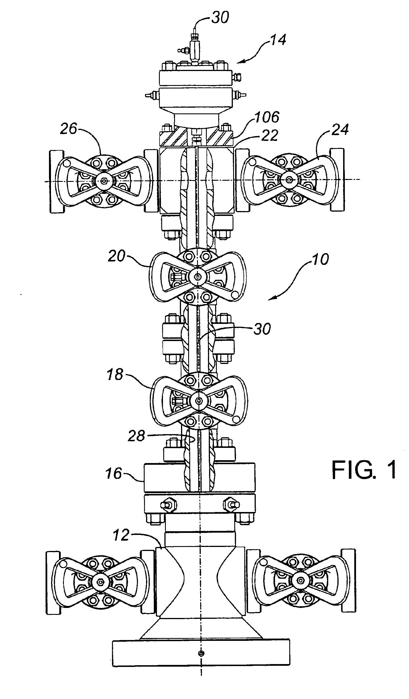
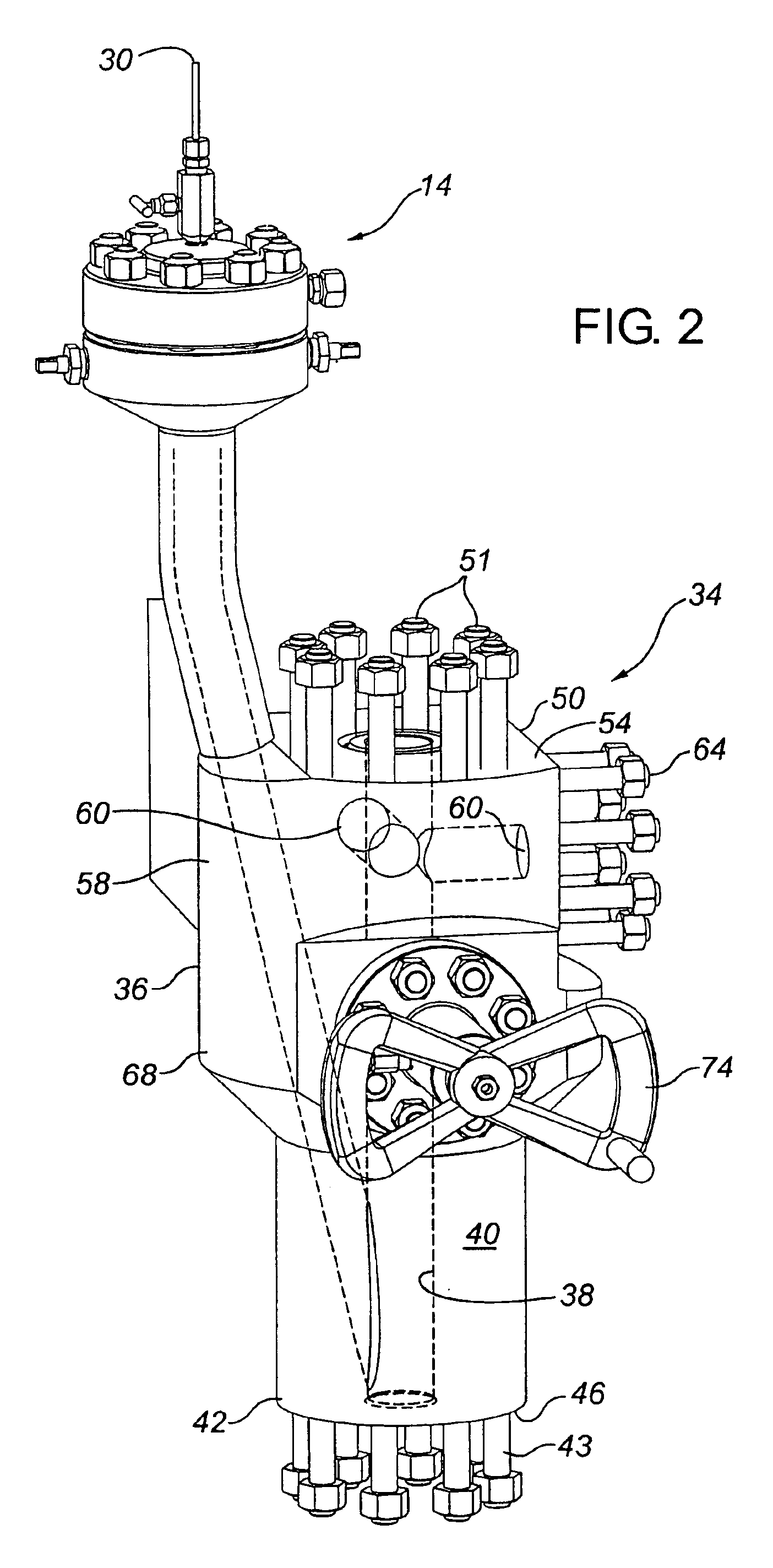
The Y-body Christmas tree of this invention is shown in FIGS. 2-5 and 7-10, while a comparable conventional prior art Christmas tree for a completed well is shown in FIGS. 1 and 6. In FIG. 1, the separate components of a conventional Christmas tree, shown generally at 10, are located between a conventional tubing head 12 and the coil tubing assembly 14 of the present invention. In FIG. 6, all components shown are as found in a conventional prior art Christmas tree. The conventional Christmas tree 10 includes sequentially, from the bottom to the top as separate, generally tubular flanged components, a tubing head adapter 16, a lower master gate valve 18, an upper master gate valve 20, and a flow tee 22. The flow tee 22 is shown to provide side access for well flow to diametrically opposed flow line gate valve 24 and kill line gate valve 26. As shown in FIG. 1, these components of the Christmas tree 10 are formed as separate components, which when connected together, provide a vertica...


PUM


Abstract

The invention provides a Y-body Christmas tree for use with coil tubing and other wellhead components which integrates components of a Christmas tree, while providing for coil tubing access without necessarily adding to the vertical height of the unit. The Y-body Christmas tree includes firstly, a body formed as a single piece of steel and forming a vertical bore extending axially therethrough, wherein the body comprises in sequence from the bottom to the top:i) a bottom connector for connecting to a wellhead component located therebelow;ii) a first valve housing section forming a side opening communicating with the vertical bore;iii) a flow tee housing section forming at least one side opening communicating with the vertical bore, for producing well flow; andiv) a top connector for connecting to a wellhead component located thereabove. The Y-body Christmas tree also includes a first shut off valve located in the first valve housing for controlling well flow through the vertical bore, a coil tubing bore formed in the body which intersects and connects to the vertical bore below the first valve, and which extends upwardly at an angle from the vertical bore sufficient to feed coil tubing; and a coil tubing head assembly communicating with the coil tubing bore for inserting, sealing and suspending the coil tubing therein.

Description

FIELD OF THE INVENTIONThe invention relates to a Y-Body Christmas Tree for use in wellheads to provide access for coil tubing.BACKGROUND OF THE INVENTIONConventional wellhead equipment used in connection with completed oil and gas production wells include, from the bottom up, a flanged casing head having an internal casing hanger from which the casing is suspended; a flanged tubing head having an internal tubing hanger from which the well tubing string is suspended; and a “Christmas tree” consisting of multiple components, the interconnected components forming a vertical fluid flow bore which extends through the components from top to bottom. The overall wellhead assembly extending upwards from the top of the tubing head is commonly referred to as the production Christmas tree. Individual components of the Christmas tree are typically flange connected and sealed to each other top and bottom and include, upwards from the tubing head, a tubing head adapter; at least one, and commonly ...

Claims


Application Information

Patent Timeline
Patent Type & Authority Patents(United States)
IPC IPC(8): E21B33/03
CPCE21B33/03
Inventor CORNELSSEN, MICHAEL JAMESLAM, TONY M.FARQUHARSON, KEITH DAVID
Owner STREAM FLO INDS
Why Eureka
Try Eureka