Retaining structure for a track device for drawers

a technology of track device and retaining structure, which is applied in the direction of drawers, furniture parts, domestic applications, etc., can solve the problems and achieve the effect of avoiding the risk of user fingers being injured

Inactive Publication Date: 2005-02-08
KING SLIDE WORKS CO LTD
View PDF13 Cites 45 Cited by
  • Summary
  • Abstract
  • Description
  • Claims
  • Application Information

AI Technical Summary

Benefits of technology

An object of the present invention is to provide a track device that avoids the r...

Problems solved by technology

As a result, the fing...

Method used


Image

  • Retaining structure for a track device for drawers
  • Retaining structure for a track device for drawers
  • Retaining structure for a track device for drawers

Examples


first embodiment

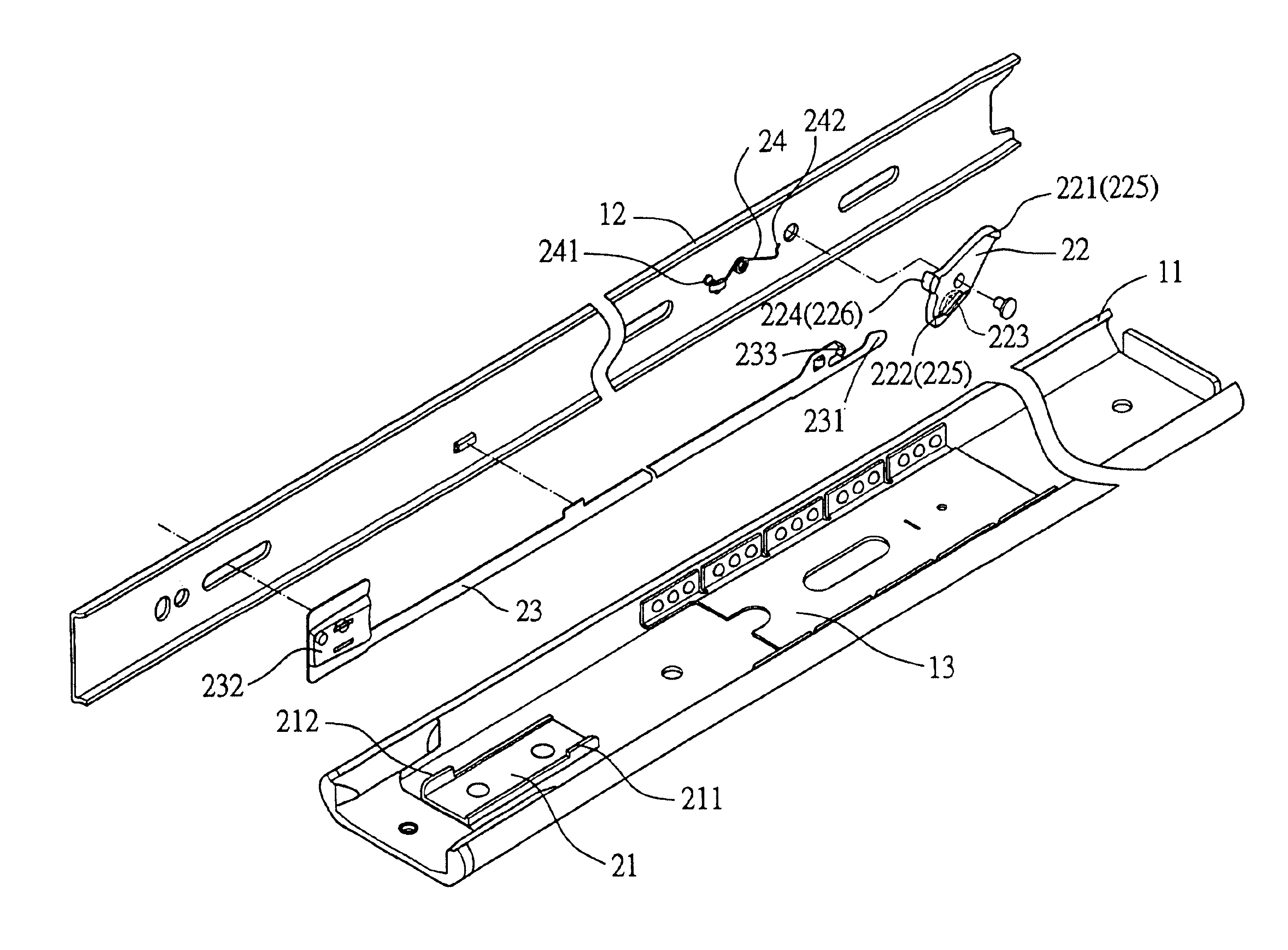
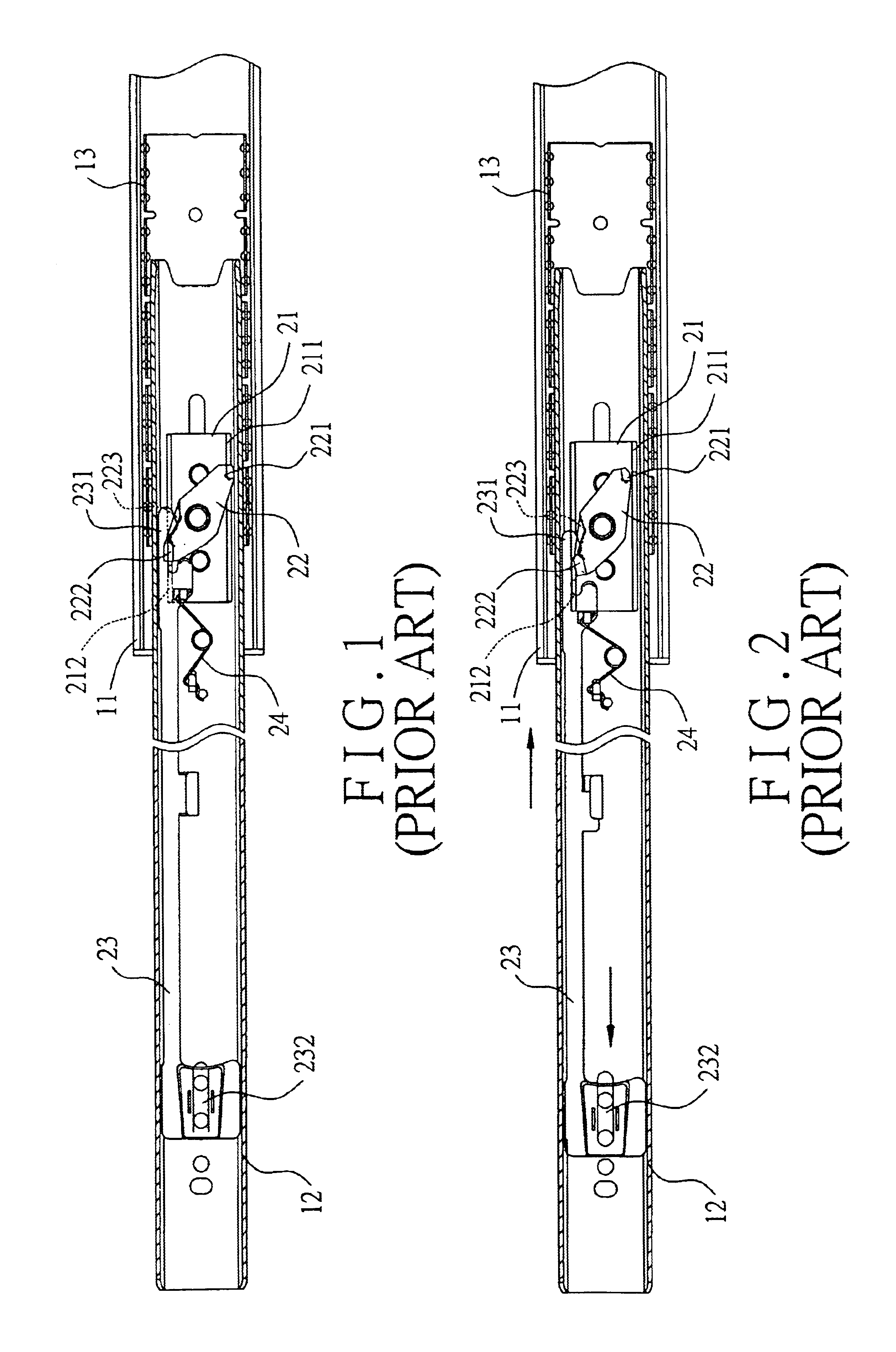
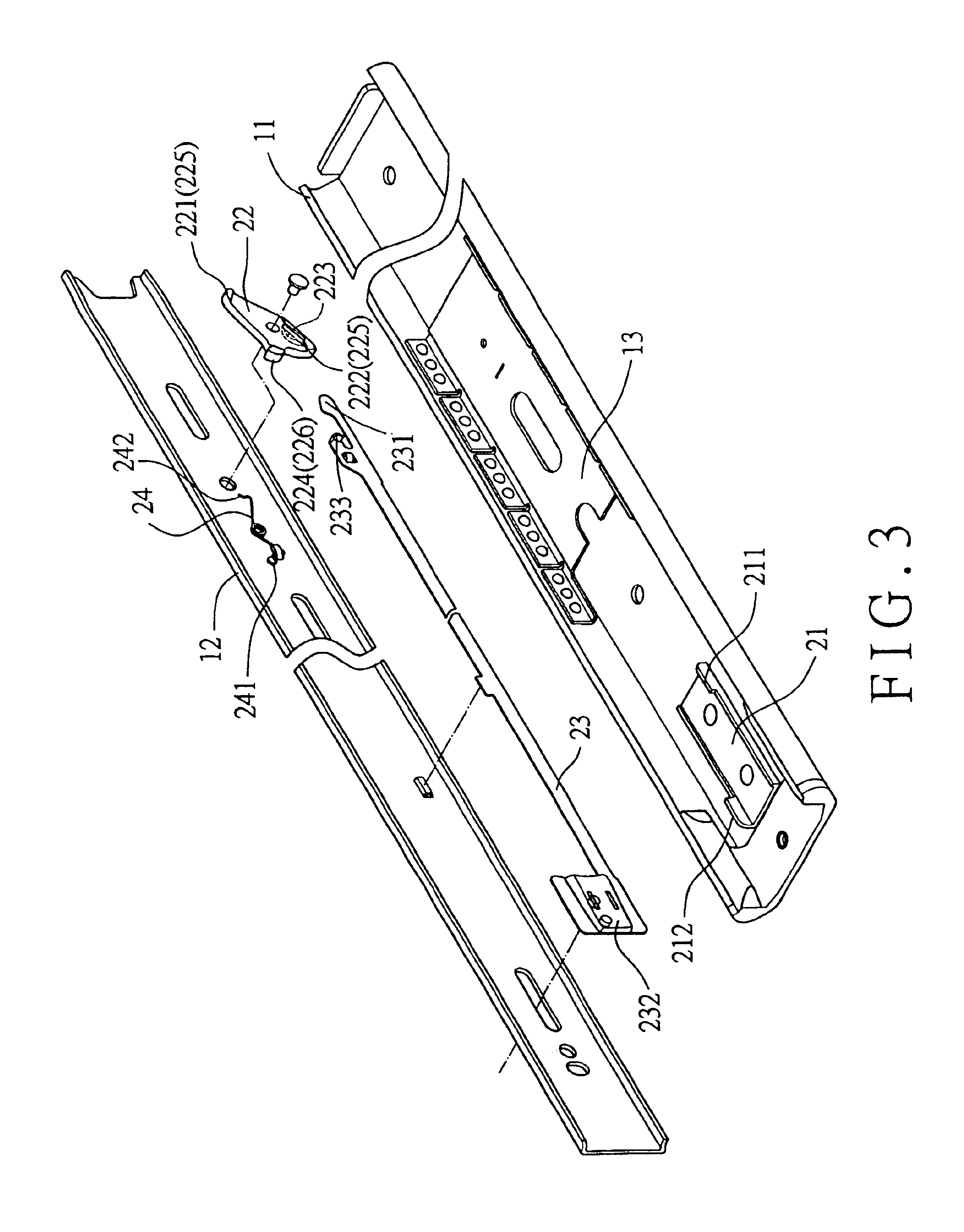
Referring to FIGS. 3 and 4, a track device in accordance with the present invention includes a first track 11 having a stop member 21 mounted thereon and a second track 12 having a limiting member 22 mounted thereon. The limiting member 22 in this embodiment is a substantially rhombic metal plate pivotally mounted to a side of the second track 12 facing the first track 11. The limiting member 22 includes two cams 221 and 222 respectively on two opposed acute-angled corners or corner portions 225 thereof for respectively cooperating with two stops 211 and 212 respectively formed on two sides of the stop member 21. The stop 212 of the stop member 21 is more adjacent to an outer end (or front end) of the first track 11 than the stop 211 is. The cam 222 of the limiting member 22 is more adjacent to the outer end of an outer end (or front end) of the second track 12 than the cam 221 is.

A slide-aiding member 13 is mounted between the first track 11 and the second track 12, allowing smooth...

second embodiment

FIG. 8 illustrates the track device in accordance with the present invention, wherein the stops (now designated by 111 and 112) are formed on the first track 11 by means of direct punching to replace the stops 211 and 212 of the stop member 21. Thus, the stops 111 and 112 not only temporarily retains the safety element 224 of the limiting member 22 for reminding the user to remove his or her fingers but also reduces the number of the elements required for the track device, the time for assembling the track device, and the cost for manufacturing the track device.

According to the above description, it is appreciated that by means of providing a safety element 224 on the limiting member 22, the user will be reminded to remove his or her fingers through engagement between the safety element 224 and the stop 211 of the stop member 21 when the connecting rod 23 is manually pulled for unlatching purposes. The risk of injury to the fingers of the user is avoided accordingly.


PUM


Abstract

A track device includes a first track, a second track slidably received in the first track, a stop member fixed on the first track, a limiting member pivotally mounted to the second track and including two cams for respectively releasably engaging with two stops of the stop member, and a connecting rod mounted on the second track. When a user manually operates the connecting rod to move the limiting member from the latching position to the unlatching position, a safety element on the limiting member comes in contact with one of the stops of the stop member when the second track is moved from the extended position into the first track and when the connecting rod is pulled, thereby preventing injury to the user's fingers that grasp the connecting rod.

Description

BACKGROUND OF THE INVENTION1. Field of the InventionThe present invention relates to a retaining structure for a track device for drawers.2. Description of Related ArtFIGS. 1 and 2 of the drawings illustrates a conventional track device with a retaining structure. The track device includes a first track 11 having a stop member 21 mounted thereon and a second track 12 having a limiting member 22 mounted thereon. The stop member 21 includes two stops 211 and 212. The limiting member 22 is pivotally mounted on the second track 12 and includes two cams 221 and 222 for respectively cooperating with the stops 211 and 212. A slide-aiding member 13 is mounted between the first track 11 and the second track 12, allowing smooth sliding movement between the first track 11 and the second track 12. The limiting member 22 further has a groove 223 for cooperating with a release cam 231 of a connecting rod 23 and an elastic element 24, thereby allowing the limiting member 22 to be manually switched...

Claims


Application Information

Patent Timeline
IPC IPC(8): A47B88/04A47B88/14
CPCA47B88/047A47B88/14A47B2210/0089A47B2210/0018A47B88/53A47B88/50A47B88/497A47B88/487A47B88/467
Inventor CHEN, KEN-CHINGWANG, CHUN-CHIANG
Owner KING SLIDE WORKS CO LTD
Why Eureka
Try Eureka