
Ink jet head, ink jet recording apparatus, and method for removing dust from the ink jet head

a technology recording apparatus, which is applied in the direction of printing, other printing apparatus, etc., can solve the problems of inability to completely prevent the entry of dust and bubbles, inability to completely discharge ink, and disadvantages of ink jet head, and achieve the effect of reliably and relatively easy removal of dust from ink

Inactive Publication Date: 2005-02-08
SEIKO INSTR INC
View PDF4 Cites 13 Cited by
  • Summary
  • Abstract
  • Description
  • Claims
  • Application Information

AI Technical Summary

Benefits of technology

It is therefore an object of the present invention to provide an ink jet head and an ink jet recording apparatus that are capable of removing dust therein reliably and relatively easily, and a method for removing dust from the head.
According to the present invention, the ink contained in the ink chamber is absorbed and discharged through the communicating passages formed in the passage forming member. This makes it possible to remove the dust from the ink reliably and relatively easily.

Problems solved by technology

The above-described ink jet head is disadvantageous because the ink cannot be satisfactorily discharged due to dust, bubbles, etc. in the ink.
Although the use of the filter 112 can prevent the entry of dust and bubbles of a certain size, it is difficult to completely prevent the entry of dust and bubbles.
Although the use of a finely meshed filter would prevent the entry of dust to a larger degree, such a filter disturbs the flow of ink.
It is therefore impossible to use a finely meshed filter.
This cleaning operation, however, cannot completely remove the dust.

Method used


Image

  • Ink jet head, ink jet recording apparatus, and method for removing dust from the ink jet head
  • Ink jet head, ink jet recording apparatus, and method for removing dust from the ink jet head
  • Ink jet head, ink jet recording apparatus, and method for removing dust from the ink jet head

Examples


Embodiment Construction

The present invention will now be described in detail with reference to the drawings showing an embodiment thereof.

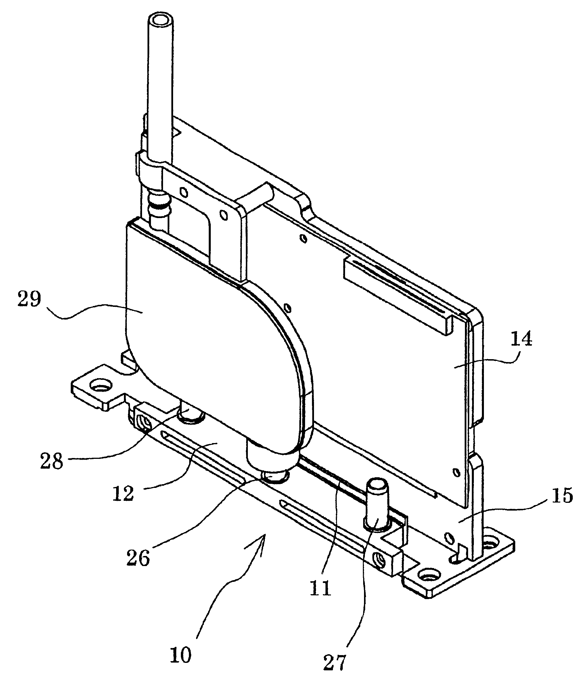
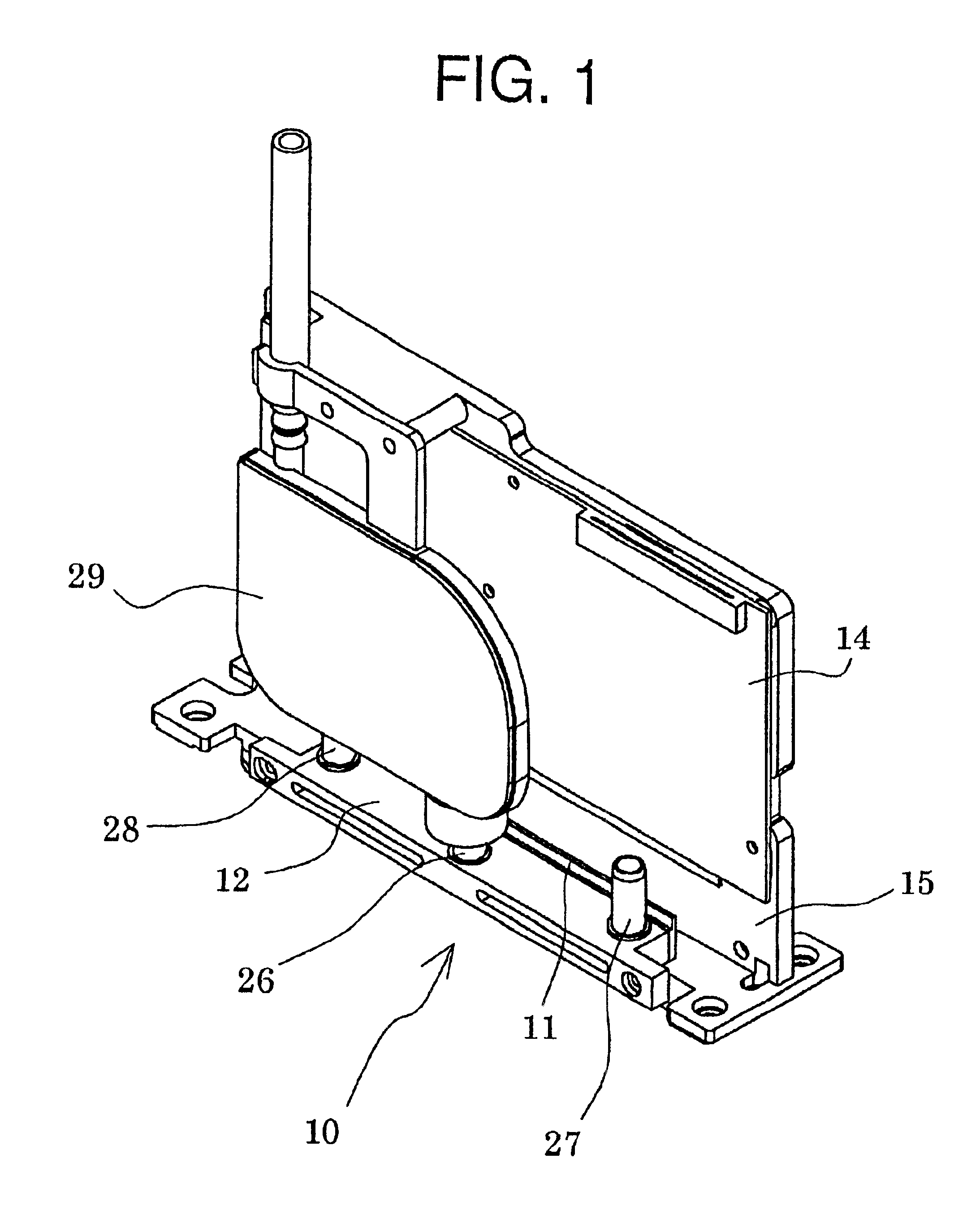
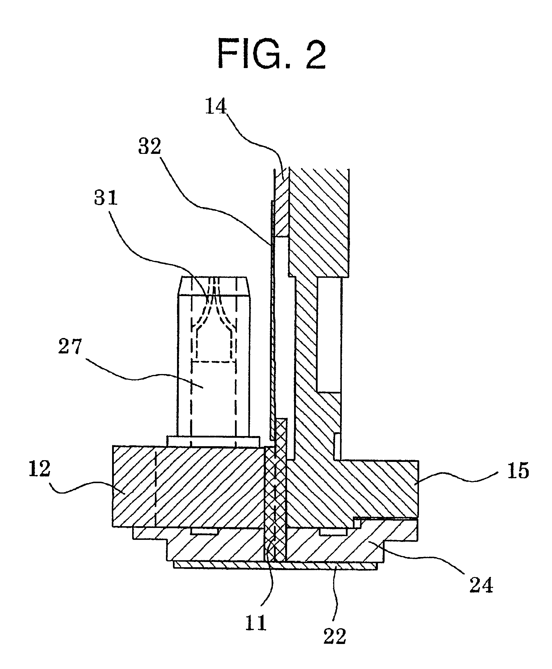
FIG. 1 is an assembly perspective view showing an ink jet head according to an embodiment of the present invention, FIG. 2 is a sectional view showing a principal part of the ink jet head, and FIGS. 3A and 3B are perspective view showing a head chip of the ink jet head.

As shown in FIGS. 1 and 2, the ink jet head 10 of this embodiment is comprised of the head chip 11, a passage forming member 12 disposed at one side of the head chip 11, and a wiring substrate 14 on which a drive circuit for driving the head chip 11 and the like are fabricated. These members are fixed to a base member 15.

First, the structure of the head chip 11 will be described. As shown in FIGS. 3A and 3B, a plurality of channels or grooves 17 are formed in parallel in a piezo-ceramic plate 16 of the head chip 11, and the grooves 17 are separated by side walls 18. On end portion of each groove 17 extend...


PUM


Abstract

An ink jet head has a substrate, partition walls disposed on a main surface of the substrate and spaced apart at a preselected interval to form channels for receiving ink. An ink chamber plate is connected to the substrate to define with the partition walls an ink chamber for supplying ink to the channels. A passage forming member is connected to the ink chamber plate and has an ink supply passage disposed in communication with the ink chamber for supplying ink contained in an ink storage device to the ink chamber and at least one ink discharge passage for discharging ink from the ink chamber. The ink discharge passage is independent from the ink supply passage so that ink is supplied directly to the ink chamber through the ink supply passage without passing through at least a portion of the ink discharge passage.

Description

BACKGROUND OF THE INVENTION1. Field of the InventionThe present invention relates to an ink jet head and an ink jet recording apparatus that prints by discharging ink droplets through nozzle apertures, and to a method for removing unwanted substances including dust particles and bubbles from the ink jet head.2. Description of the Related ArtThere is known a conventional ink jet recording apparatus that records characters and images on a recording medium by using an ink jet head having a plurality of nozzles for discharging ink. In this ink jet recording apparatus, the nozzles of the ink jet head are formed in a head holder in such a position as to face the recording medium. The head holder is mounted on a carriage and performs scanning in a direction perpendicular to a transport direction of the recording medium.FIG. 7 is an exploded schematic diagram showing an example of such an ink jet head. As shown in FIG. 7, a plurality of grooves 102 are formed in parallel in a piezo-ceramic ...

Claims


Application Information

Patent Timeline
Patent Type & Authority Patents(United States)
IPC IPC(8): B41J2/14B41J2/165B41J29/17B41J2/055B41J2/045
CPCB41J2/14209B41J2/16552B41J29/17B41J2002/14419B41J2002/14403
Inventor TOMINAGA, KAZUYOSHI
Owner SEIKO INSTR INC
Learn More