

Ophthalmic lenses with reduced chromatic blur
a technology of chromatic blur and ophthalmology, applied in the field of ophthalmology, can solve the problems of increasing chromatic aberration or color dispersion, affecting the wearer, and affecting the wearer's comfort,
- Summary
- Abstract
- Description
- Claims
- Application Information
AI Technical Summary
Problems solved by technology
Method used
Image

Examples
example 1
A single vision lens with −4.00 diopters of spherical power is made from polycarbonate with an Abbe number of 29. As a baseline for comparison purposes, a conventional refractive lens is first analyzed, which lens has a front radius of 200 mm and back radius of 79 mm. The lens is analyzed by computing the RMS spot size at the focal plane of an 18 mm focal length lens placed at the eye rotation point 27 mm from the lens. The RMS spot size is computed for input angles from −40 to +40 degrees and is shown in FIG. 3.
A diffractive element with a power of −0.37 diopters is placed on the back, concave, surface of the lens. To maintain the spherical power, the radius of the back surface is changed to 89 mm. The RMS spot size for this diffractive / refractive lens is shown in graphical form in FIG. 4. The image quality at x=0, y=0 improved as measured by the decrease in spot size from approximately 0.004 mm to 0.001 mm. This is due primarily to an improvement in the axial, or longitudinal, abe...
example 2
A polycarbonate, non-toric, progressive addition lens is provided with a distance power of −4.00 diopters and an add power of 1.30 diopters. In FIG. 5 is depicted the RMS spot size for the lens. In FIG. 4 is depicted the unwanted astigmatism in the lens. In both of these figures is shown cross-sectional analysis through horizontal cuts through the lens at various angles. The 10-degree cross-section is a horizontal cut through the far vision region of the lens. In this particular lens, the near vision region is at −40 degrees. A series of cuts is made from the far vision region through the intermediate vision region and to the near vision region.
A diffractive grating with a −0.35 diopters of power is added on the concave surface of the lens. The overall sphere power remains −4.00 diopters, but the refractive portion of the sphere power was reduced to −3.65 diopters. The Abbe number of the diffractive portion of the lens was approximately −3.5 and that of the refractive portion 29. As...
example 3
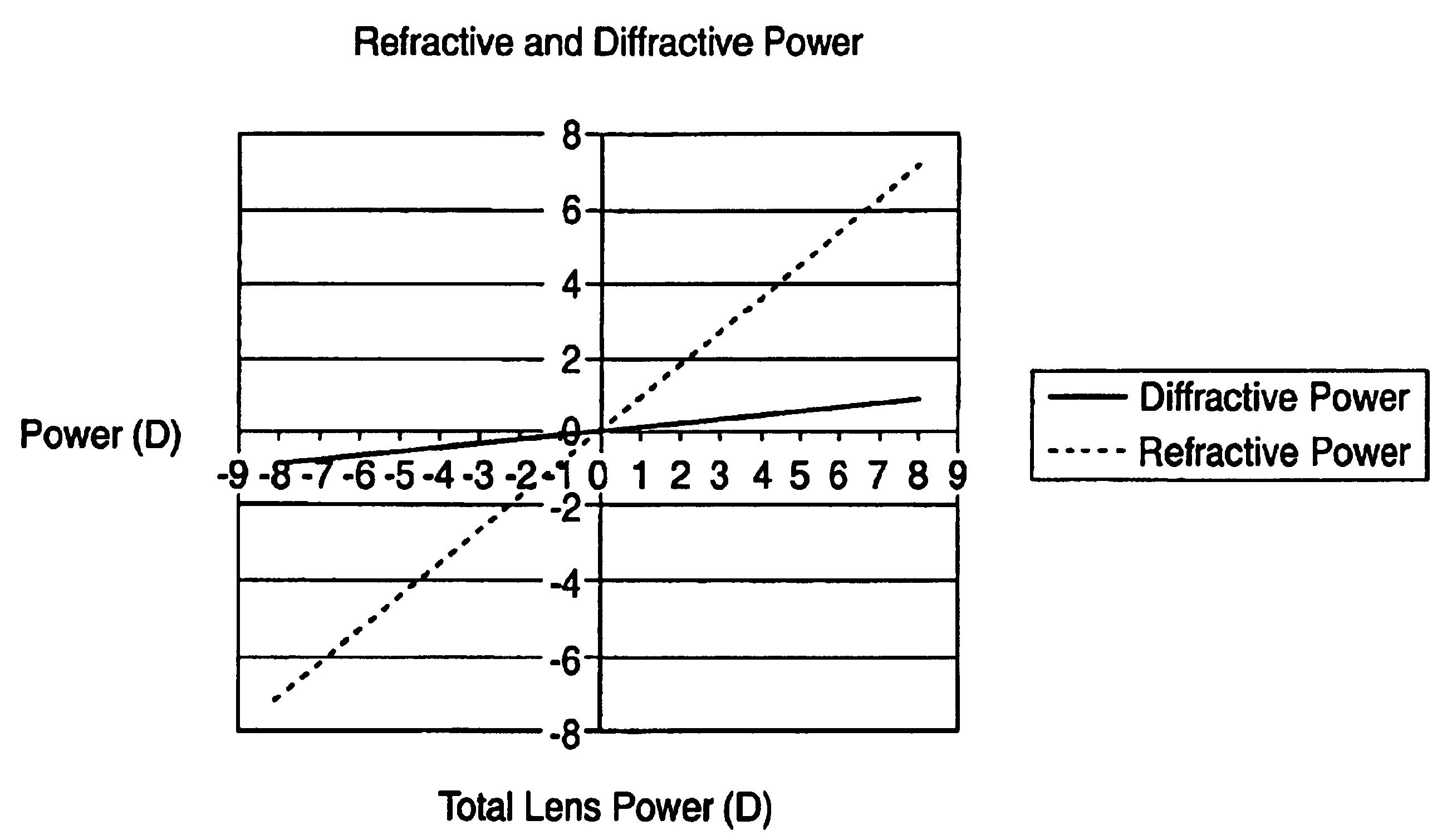
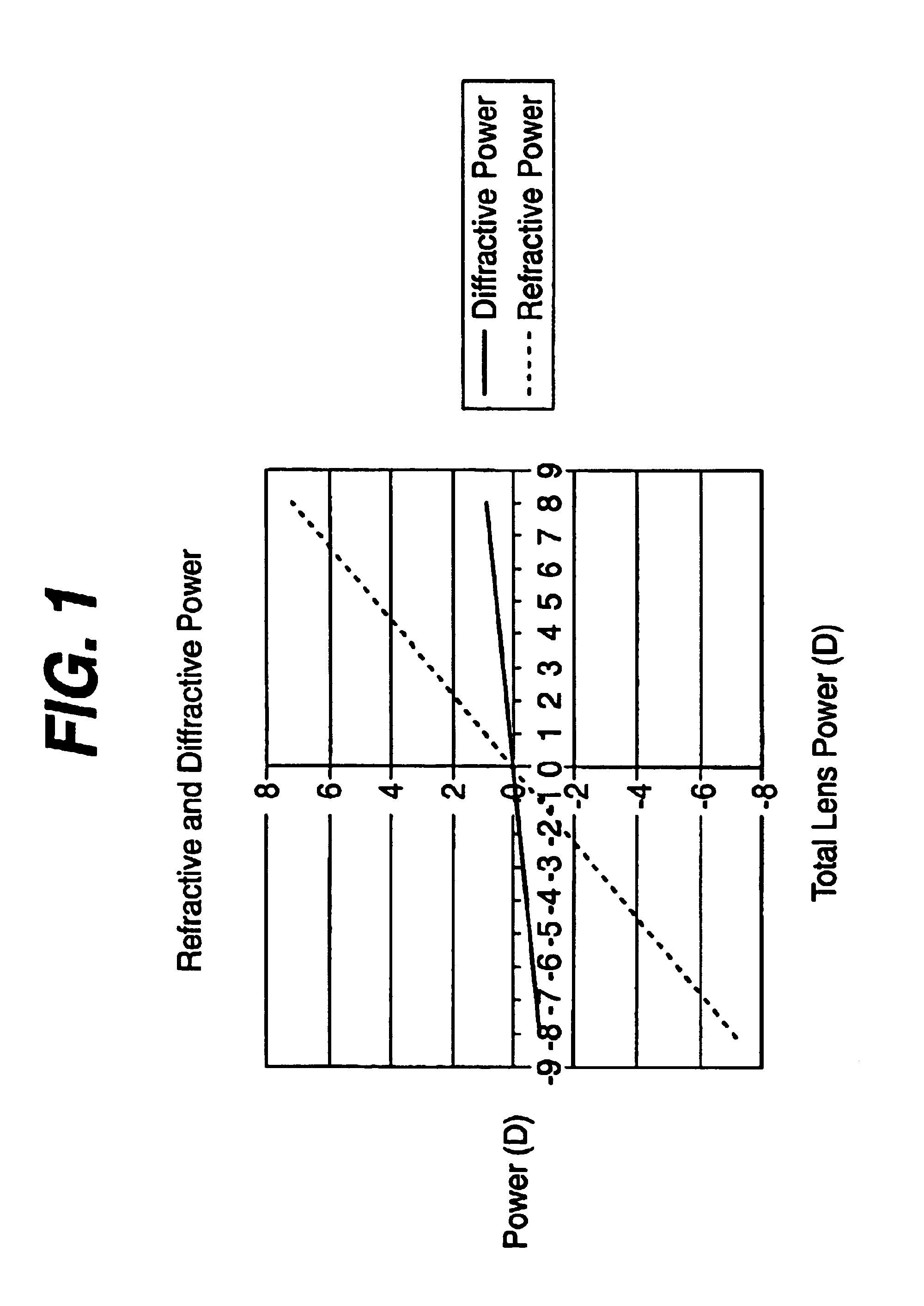
The diffractive power for a family of designs can be chosen so that a unique diffractive is not required for each sphere power. The total spherical power for a lens is the sum of the refractive power of the front surface plus the refractive power of the back surface plus the diffractive power of the diffractive element, whether it is applied to the front, back, or to an intermediate surface.
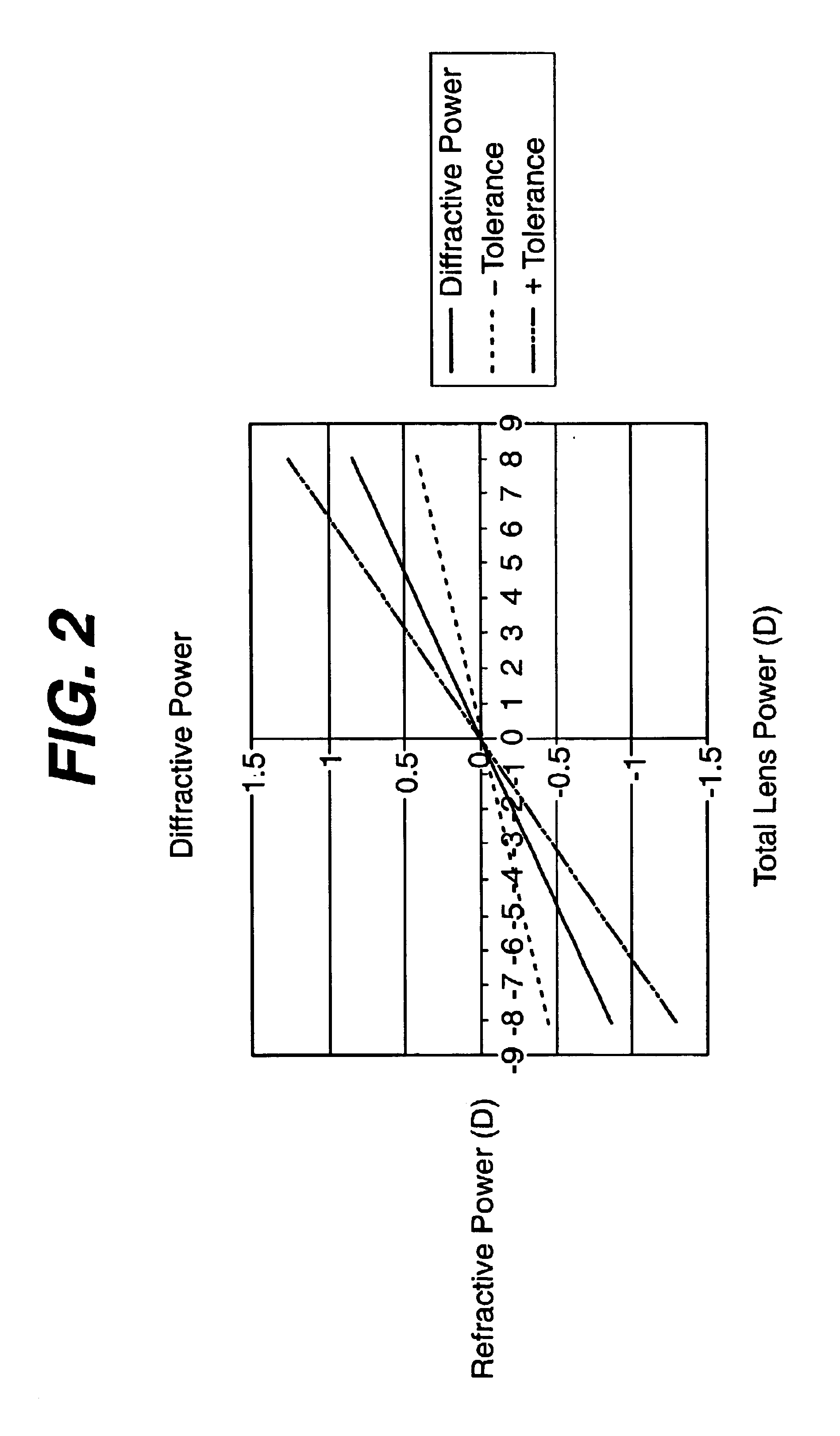
Table 2 shows the front refractive, back refractive, and diffractive powers for a family of designs for single vision lenses made from polycarbonate that will provide improved chromatic performance because of the diffractive power provided on five of six unique front curves (9, 8, 6, 4, 2, and 1 Diopters). For each sphere power there is a unique back curve. The transverse chromatic aberration at a height of 15 mm on the lens is also shown. The diffractive power was chosen for each of the six unique front curves to give the minimum TCA over the range of sphere powers covered by that case. For the ...
PUM
 Abstract
Description
Claims
Application Information