Light emitting diode lamp having parabolic reflector and diffuser

a technology of parabolic reflector and light-emitting diode lamp, which is applied in the field of light-emitting diode lamps having parabolic reflector and diffuser, can solve the problems of fixture scraping or bending during maintenance, high cost of maintenance and replacement, and disruption to the occupants

Inactive Publication Date: 2005-02-08
LEYSATH JOSEPH A
View PDF22 Cites 129 Cited by
  • Summary
  • Abstract
  • Description
  • Claims
  • Application Information

AI Technical Summary

Problems solved by technology

The cost to conduct such maintenance and replacement can be expensive as well as disruptive to the occupants.
Lighting fixtures also deteriorate over time.
Fixtures, and particularly metal fixtures, can be scraped or bent during maintenance or when an object strikes the fixture.
This deterioration over time reduces fixture performance and fixture aesthetics.
In addition to maintenance, the cost of operating a fixture is tied directly to its energy use.
Typically these light sources appear as dots, which are not visually appealing and tend to not meet the criteria for illumination appearance desired by most users.

Method used


Image

  • Light emitting diode lamp having parabolic reflector and diffuser
  • Light emitting diode lamp having parabolic reflector and diffuser
  • Light emitting diode lamp having parabolic reflector and diffuser

Examples


Embodiment Construction

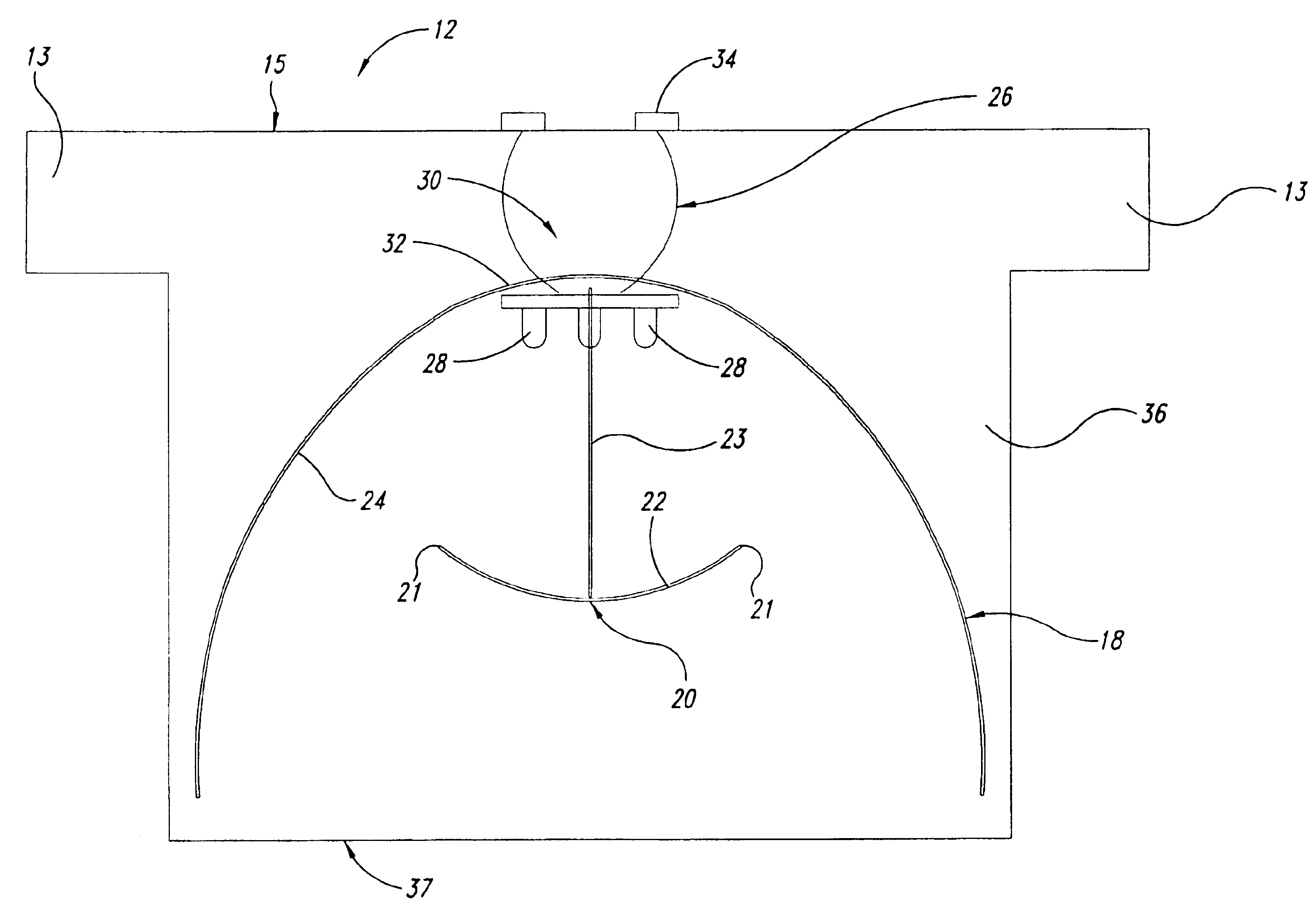
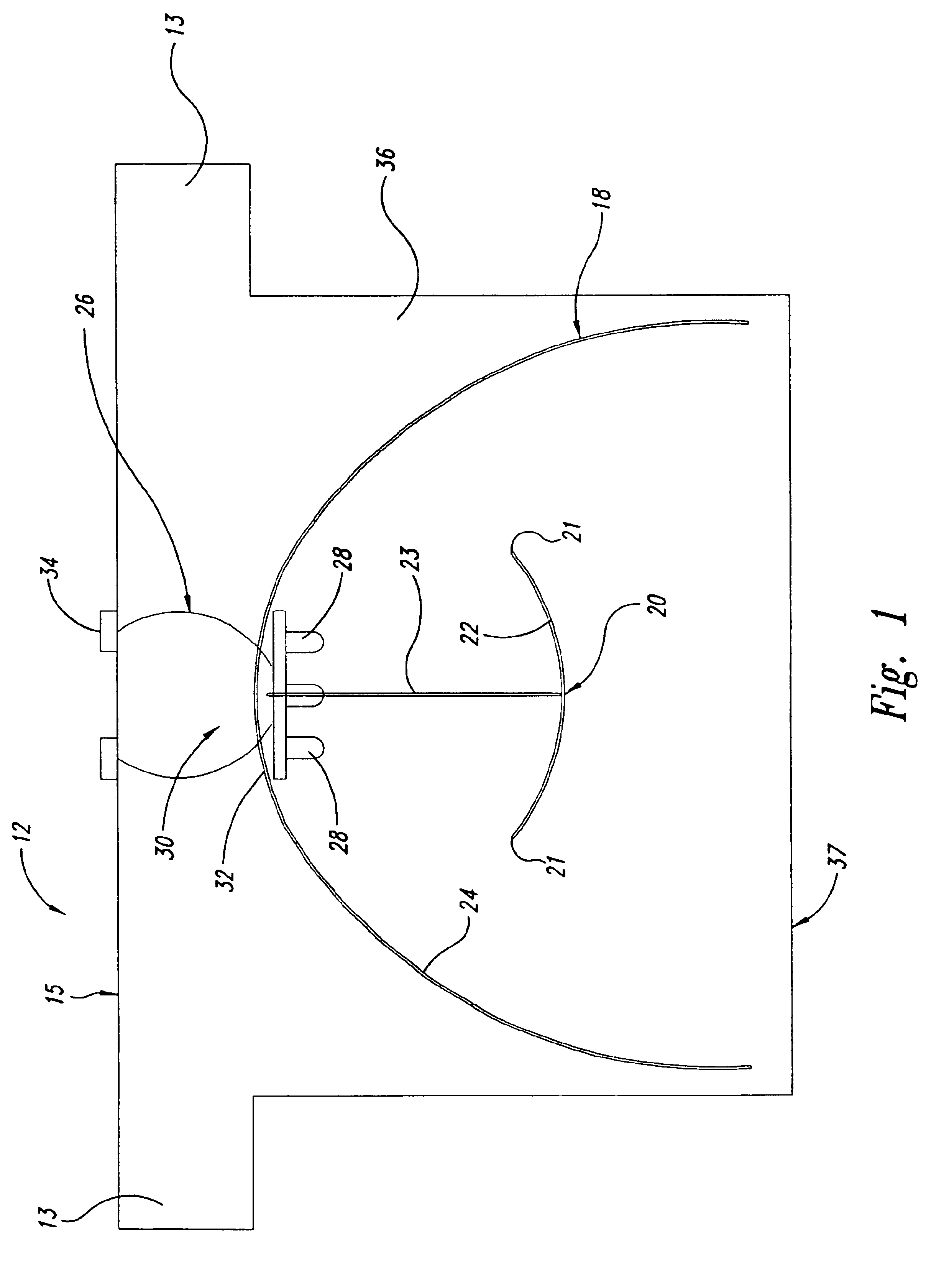
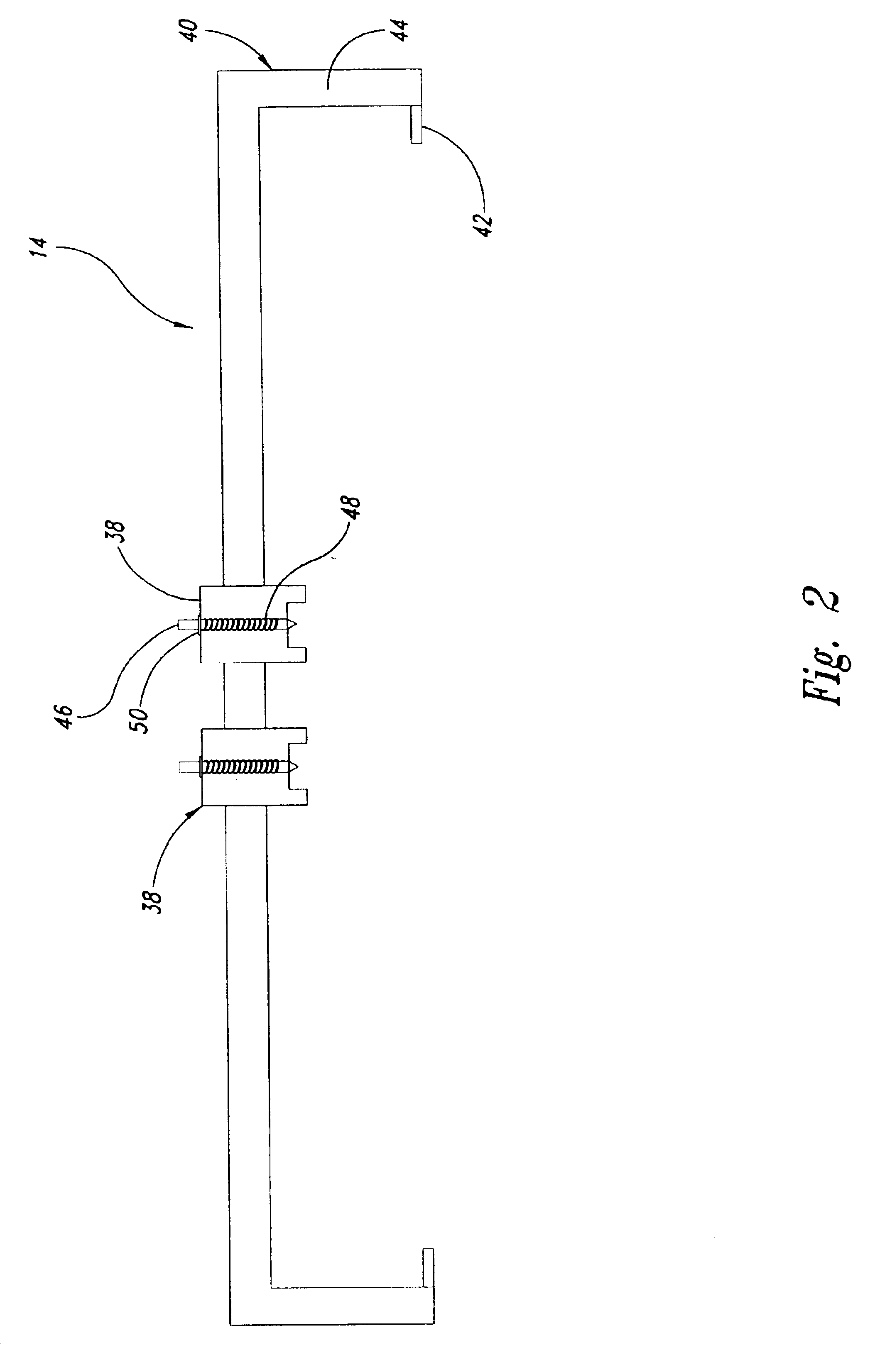
An LED light fixture 10 is shown in FIG. 3 that includes multiple LED packaging systems 12 (shown more clearly in FIG. 1) resting within multiple sockets 14 (shown in detail in FIG. 2) that are all enclosed within a housing 16.

As shown in FIG. 1, the LED packaging system 12 consists of a parabolic-shaped reflector 18 that is curved and has a cluster of LEDs 28 mounted within the reflector 18 in the center of the parabola. At a focal point of the reflector 18 is a diffuser 20 configured to have a curved shape with an inner, concave, face 22 facing an inner, concave, face 24 of the reflector 18. The diffuser 20 is shaped and configured to prevent light from the LED's from exiting the reflector 18 without reflecting from at least one surface of the reflector 18. Outer rims 21 of the diffuser 20 extend to a point that light from the LED's passing the rims 21 must strike the face 24 of the reflector 18. The inner face 22 of the diffuser 20 may be polished to reflect light back to the par...


PUM


Abstract

A light fixture consists of one or more light emitting diode (LED) packaging systems within a housing. Each LED packaging system includes one or more LED light sources that simultaneously shines onto opposing reflecting surfaces, then shines forward through encapsulation material. The housing consists of a cluster of prewired sockets with an outer reflective surface. Electrical wiring runs from the rear of the first socket and then to an adjacent socket in a daisy chain fashion. Each socket includes connectors configured to provide each LED packaging system with a source of electricity. The housing has diffusers that adjust the light to an evenly distributed appearance.

Description

BACKGROUND OF THE INVENTION1. Field of the InventionThe disclosed embodiments of the invention relate generally to lighting fixtures used for illumination purposes, and more particularly, to lighting fixtures used in buildings for the purpose of general illumination and accent illumination.2. Description of the Related ArtGeneral illumination in buildings is primarily from lighting fixtures. These lighting fixtures use either fluorescent, incandescent or a HID lighting source.When a lighting source lamp burns-out, it must be replaced. Typically, a fluorescent lamp will need to be replaced every 15,000 hours, an incandescent lamp every 2000 hours, and an HID lamp every 20,000 hours. Associated ballast replacement occurs about every five years. The cost to conduct such maintenance and replacement can be expensive as well as disruptive to the occupants.Lighting fixtures also deteriorate over time. Fixtures, and particularly metal fixtures, can be scraped or bent during maintenance or w...

Claims


Application Information

Patent Timeline
Patent Type & Authority Patents(United States)
IPC IPC(8): F21S8/04F21V13/00F21V13/10F21V7/00
CPCF21S8/04F21V13/10F21V7/0008F21Y2103/003F21W2131/40F21Y2101/02F21Y2103/10F21Y2115/10F21Y2113/00
Inventor LEYSATH, JOSEPH A.
Owner LEYSATH JOSEPH A
Why Eureka
Try Eureka