Electronic fever thermometer

Inactive Publication Date: 2005-02-08
MICROLIFE INTPROP GMBH
View PDF22 Cites 18 Cited by
  • Summary
  • Abstract
  • Description
  • Claims
  • Application Information

AI Technical Summary

Benefits of technology

The task of the present invention is to avoid the drawbacks of the known solutions, especially to devise a fever thermometer that can be simply and economically produced, which guarantees optimal watertightness and is simple to clean and disinfect. The fever thermometer should also be reliable during long-term use.
The housing according to the invention has an outer and / or inner surface, which is machined, preferably structured, so that the housing is essentially nontransparent to visible light. The housing is not machined in at least one viewing area and is therefore transparent. The display element is arranged in the interior of the housing adjacent to the viewing area. Owing to the treated outer and / or inner surface the housing is essentially nontransparent so that the components in the interior of the thermometer are not apparent. Only in the region of the display element is the housing transparent. An essentially nontransparent housing can therefore be produced in one piece without having to use a viewing window separately in the area of the display element, as in known fever thermometers. On the one hand, this permits more economical manufacture. On the other hand, owing to the smooth surface without joints, disinfection of the fever thermometer is simpler and guarantees watertightness. In addition, costly coating (not resistant during use) of the surface with paint or another coating is avoided.
The housing is also preferably provided with a metal tip that can be glued into the housing. The temperature sensor in this case is arranged within this metal tip. The metal tip permits rapid heat transfer between the tissue whose temperature is to be measured and the temperature sensor.
A roughened inner surface has the advantage that the outer surface can be left smooth. A smooth surface is more pleasant for the user.
The electronic fever thermometer is provided with a battery. A long-term battery is preferably used, which is advantageously welded unreplaceably into the housing. The watertightness is thus increased and the reliability of the fever thermometer improved. The fever thermometer is thus designed as a disposable thermometer. The battery is preferably welded into the housing. This design also has a positive effect in terms of manufacturing costs. The battery cover, moving contacts and the like can be dispensed with.

Problems solved by technology

However, a problem in mercury thermometers is the toxicity of mercury.
However, such thermometers are relatively expensive and are not unobjectionable in terms of toxicity.
The temperature display must also be reset by shaking, which requires considerable expenditure of force in the light gallium solutions.
Ordinary electronic fever thermometers are beset with the drawback that breaks in the surface exist between the housing and the opening inserted in it for the viewing temperature reading, which poses problems with respect to sealing and disinfectability.
A shortcoming of this thermometer is that the manufacturing and material costs are too high.
Moreover, the electronic components are visible, which imparts an unattractive appearance to the thermometer.
The visibility of the electronic components, as well as the vulnerability to breakage, are also a drawback of this known thermometer.

Method used


Image

  • Electronic fever thermometer
  • Electronic fever thermometer

Examples


Embodiment Construction

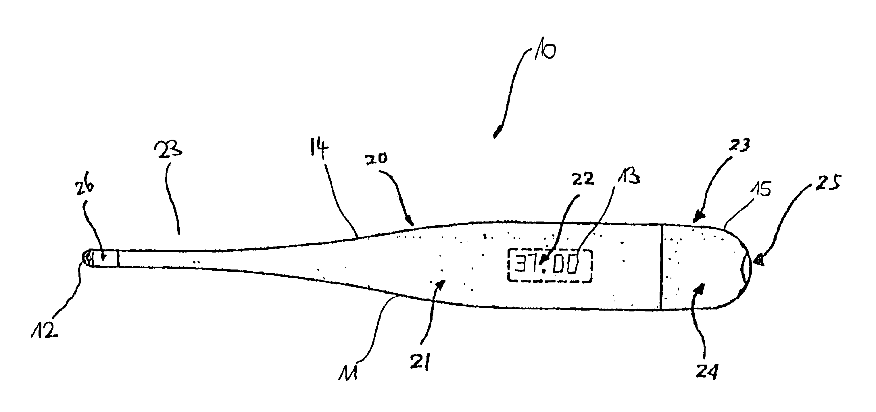
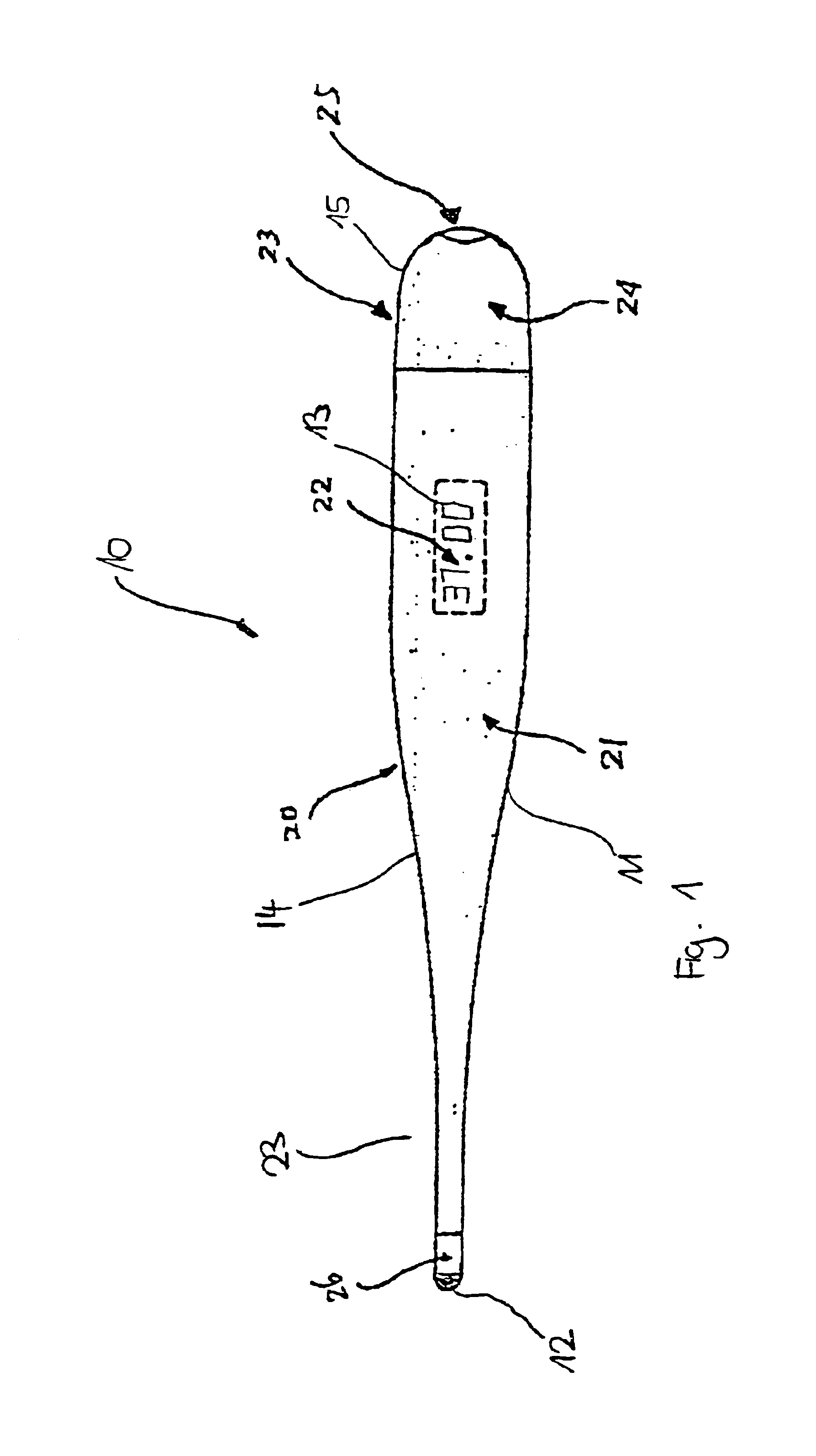
The electronic fever thermometer 10 consists essentially of a housing 11. The housing tapers on one side to a tip 23. A metal housing 26 is arranged on tip 23, preferably glued into the housing. A temperature sensor 12 for measurement of the temperature is provided in the interior of metal housing 26. The metal tip facilitates heat transport between the tissue whose temperature is to be measured and the temperature sensor 12.

The housing 11 is also provided with a switch 25. The switch 25 is inserted in an opening on housing 11. The housing can consist of a main part 14 and a battery cover 15. The battery cover 15 is preferably welded tight to the main part 14 so that watertightness is guaranteed.

A battery (not shown) is inserted into housing 11. The main part 14 and the battery cover 15 are then permanently welded to each other. Before welding, the other electronic components essential for operation are also inserted into housing 11. In particular, these are the temperature sensor 1...


PUM


Abstract

An electronic fever thermometer includes a housing made of a transparent material, for example, transparent plastic. The housing includes a temperature sensor to measure the temperature, and a display element to display the measured temperature. The housing has a treated outer and / or inner surface so that the housing is essentially nontransparent to visible light. The housing also has an untreated viewing area. The display element is arranged within the housing adjacent to the viewing area.

Description

CROSS-REFERENCE TO RELATED APPLICATIONThis application claims the benefit and priority of German Application No. 298 20 206.9, entitled ELEKTRONISCHES FIEBERTHERMOMETER, filed on Nov. 11, 1998, and issued on Feb. 25, 1999, the disclosure of which is incorporated herein by reference.BACKGROUND OF THE INVENTION1. Field of the InventionThis invention relates generally to electronic fever thermometers.2. Description of the Prior ArtFever thermometers are used to measure the temperature of the human body. Ordinary mercury thermometers in which the temperature is determined by expansion of mercury, as well as electronic thermometers, are known. The temperature is converted to an electrical signal in an electronic thermometer by an electronic component. Heat-dependent electrical resistors are generally used.Such fever thermometers must meet various requirements primarily when used in the clinical field.Since thermometers are often destroyed or stolen, the lowest possible manufacturing cost...

Claims


Application Information

Patent Timeline
IPC IPC(8): G01K1/08G01K7/00
CPCG01K1/083G01K13/25G01K1/028
Inventor LEE, YUNG KU
Owner MICROLIFE INTPROP GMBH
Why Eureka
Try Eureka