Fluorescent bulb retaining spring

Inactive Publication Date: 2005-11-10
VOSSLOH-SCHWABE
View PDF7 Cites 5 Cited by
  • Summary
  • Abstract
  • Description
  • Claims
  • Application Information

AI Technical Summary

Benefits of technology

[0005] With this as the point of departure, it is the object of the present invention to create a fluorescent bulb retaining

Problems solved by technology

If they have a base on only one end, they cannot readily be mounted in a horizontal position.
Otherwise, such bending stresses could cause considerable damage and attendant complaints.
However, a UV-resistant plastic

Method used


Image

  • Fluorescent bulb retaining spring
  • Fluorescent bulb retaining spring
  • Fluorescent bulb retaining spring

Examples


Embodiment Construction

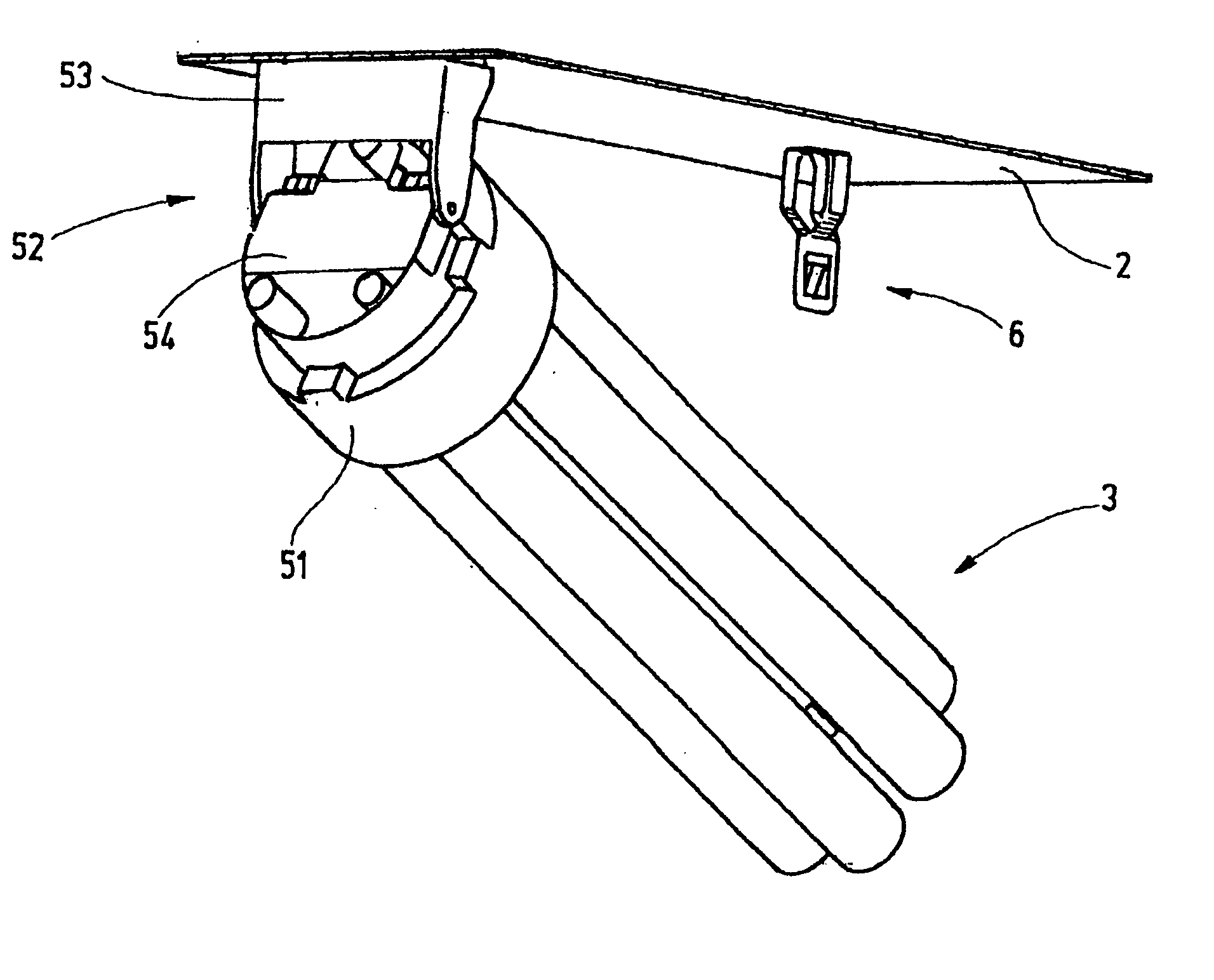
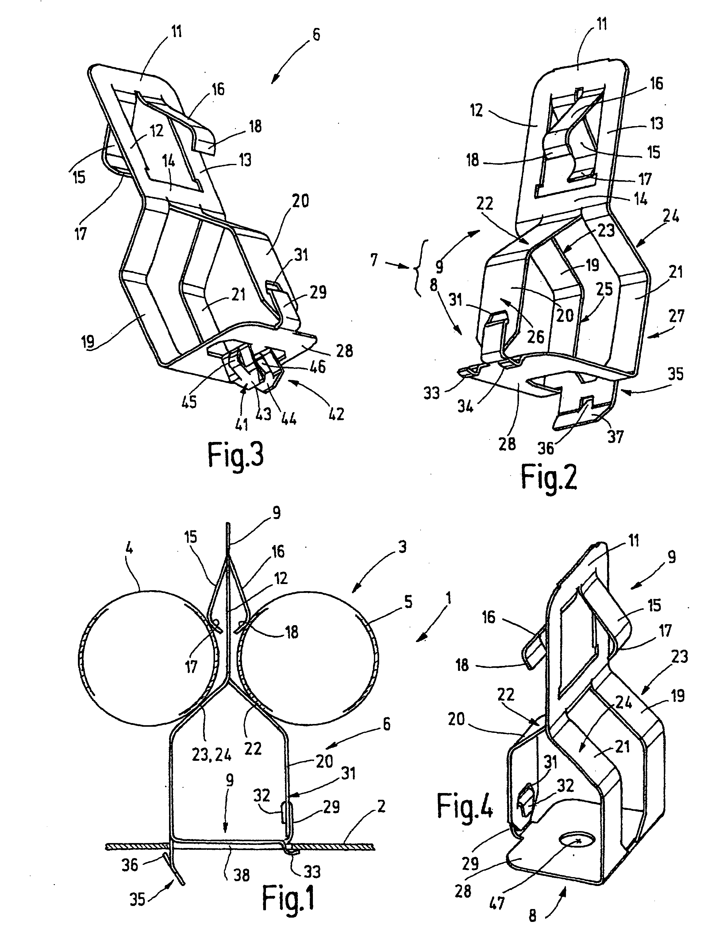
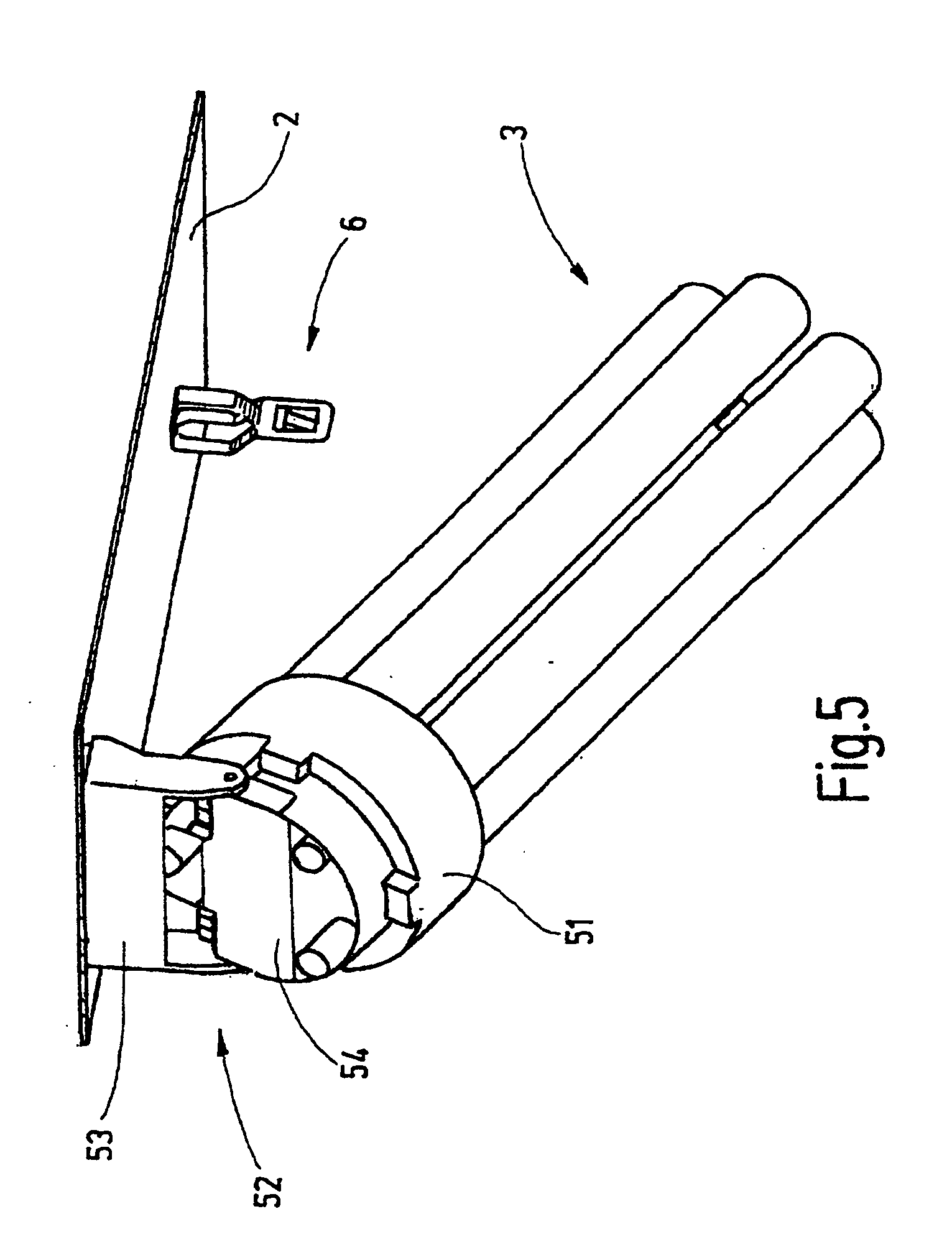
[0015] The fluorescent bulb retaining spring of the invention is embodied in one piece of resilient metal. The one-piece production can be done in a stamping and bending process, so that the retaining springs can be produced in their final form by machine, without requiring subsequent assembly or other subsequent work operations. The retaining spring has a fastening portion and a bulb retainer portion. In this respect, it is shaped in a special way and in its entirety is in one piece. It has no UV-vulnerable parts whatever. Accordingly, even after long use, no plastic parts that could have become brittle can break off. On the contrary, secure seating of the fluorescent bulbs and the relief of both the base and socket of the bulb are assured over a long period of time.

[0016] Moreover, the one-piece mode of construction of the fluorescent bulb retaining spring, including all the functional elements, enables not only especially rational production, but also simple, rational installati...


PUM


Abstract

A fluorescent bulb retaining spring (6) comprises a one piece, sheet-metal stamped and bent part, entirely and seamlessly comprised of one material. The retaining spring (6) can be produced especially simply from one rectangular piece of sheet metal of substantially uniform thickness, with all functional parts and functional regions created by cutting out spring tongues and bending them outwardly from the sheet. Connecting legs between a bulb retainer portion (9) and a fastening portion (8) form an annular region which is closed in force-locking fashion by a crimped connection (29, 31, 32), which can be produced in automated fashion as part of the stamping and bending operation.

Description

CROSS-REFERENCE TO RELATED PATENT APPLICATIONS [0001] The right of foreign priority is claimed under 35 U.S.C. § 119(a) based on Federal Republic of Germany Application No. 10 2004 021 938.9, filed May 4, 2004, the entire contents of which, including the specification, drawings, claims and abstract, are incorporated herein by reference. BACKGROUND OF THE INVENTION [0002] Fluorescent bulbs with a base or cap on one end, so-called compact fluorescent bulbs, are often quite long. If they have a base on only one end, they cannot readily be mounted in a horizontal position. An additional retaining device is necessary, which braces the end of the discharge tube that is diametrically opposite the base, which for instance is bent in a U, so that bending stresses can be kept away from both the base and the socket of the bulb. Otherwise, such bending stresses could cause considerable damage and attendant complaints. [0003] In the industry, it is known to brace the ends of fluorescent bulbs ha...

Claims


Application Information

Patent Timeline
IPC IPC(8): F21V19/00
CPCF21Y2103/00F21V19/009
Inventor KAIN, BURKHARDMEWS, HANS-PETER
Owner VOSSLOH-SCHWABE
Why Eureka
Try Eureka