
Implement for abrading and method of making same

Active Publication Date: 2005-02-08
ALI IND LLC
View PDF9 Cites 8 Cited by
  • Summary
  • Abstract
  • Description
  • Claims
  • Application Information

AI Technical Summary

Benefits of technology

It is another object to enhance the ease of use of abrading implements while maintaining effectiveness of the same in a cost efficient manner.
Accordingly, one aspect of the present invention is directed to a method of making an abrading implement. The method includes the steps of disposing a porous member for aiding in abrasion adjacent a first surface within a mold and supplying two reactive liquid components into the mold in a manner in which the two materials enter onto a second surface of the mold opposing the first surface, whereupon a reaction between the components form a raw implement of structural foam which is bonded to the porous member. Subsequent to the reaction, the raw implement is removed from the mold and cut, preferably sawn, in a manner to provide an abrasive implement having a surface portion the foam exposed from the cut to aid in gripping the same by one's hand.

Problems solved by technology

The rubber material previously employed in these blocks was relatively rigid, dense and heavy and thus difficult for the user to pry apart and / or use for long period of time without fatigue.
While these changes have been helpful in gripping the implement and reducing fatigue, these products are relatively expensive to manufacture.

Method used


Image

  • Implement for abrading and method of making same
  • Implement for abrading and method of making same
  • Implement for abrading and method of making same

Examples


Embodiment Construction

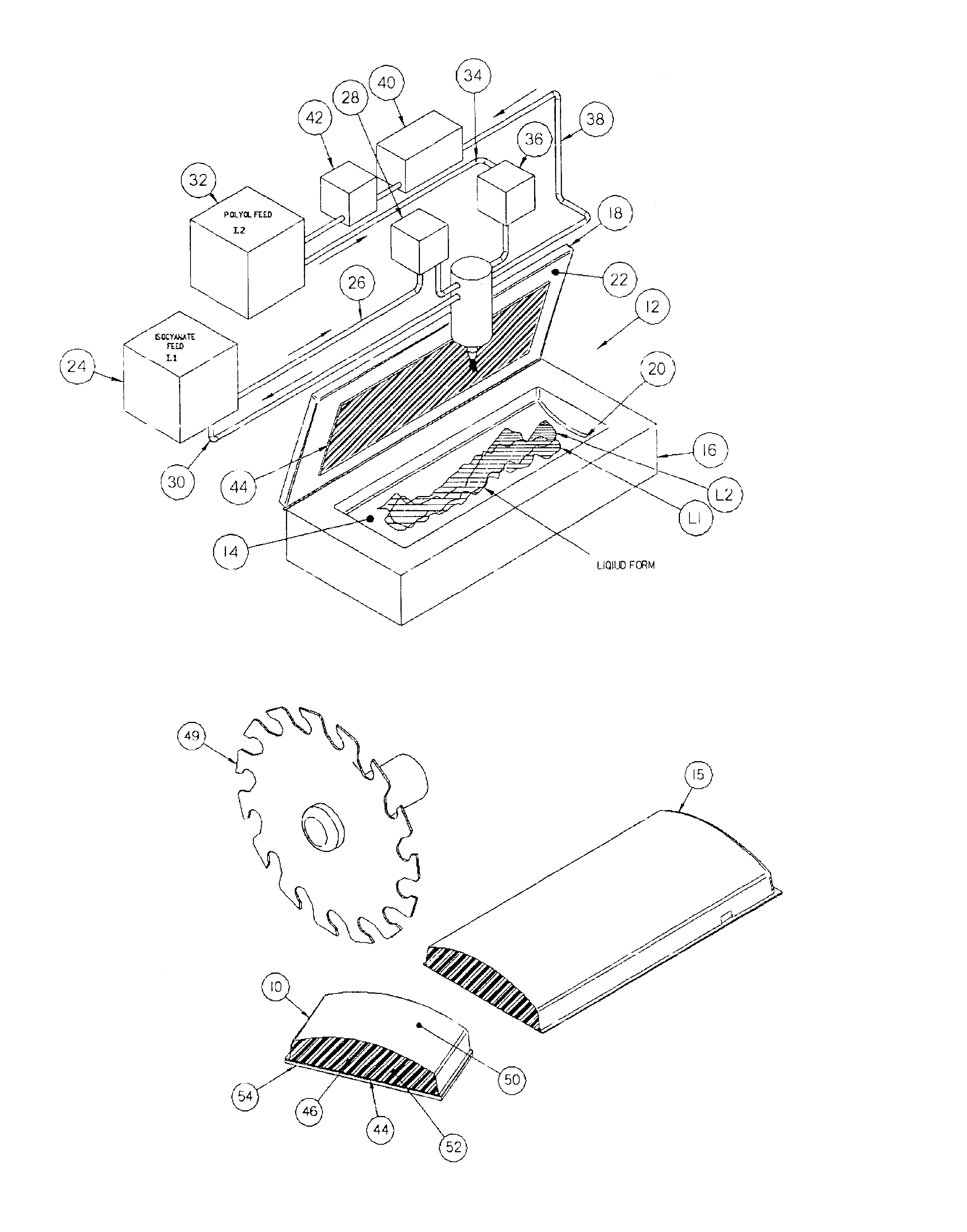
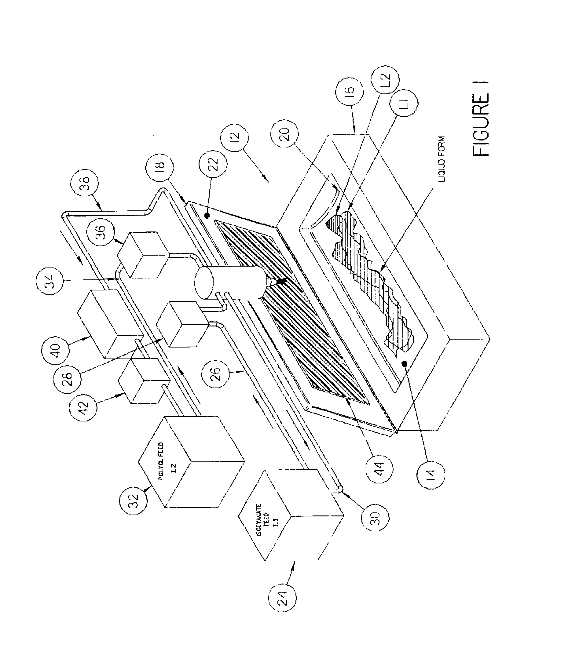
Referring now to the drawings in FIGS. 1-6, the abrading implement of the present invention is generally referred to by the numeral 10. The abrading implement 10 is formed via a molding process, preferably using Reaction Injection Molding (or RIM). The process is one in which two reactive liquid components, a polyol and an isocyante, for example are metered, blended together, and injected into a closed mold at low pressure.

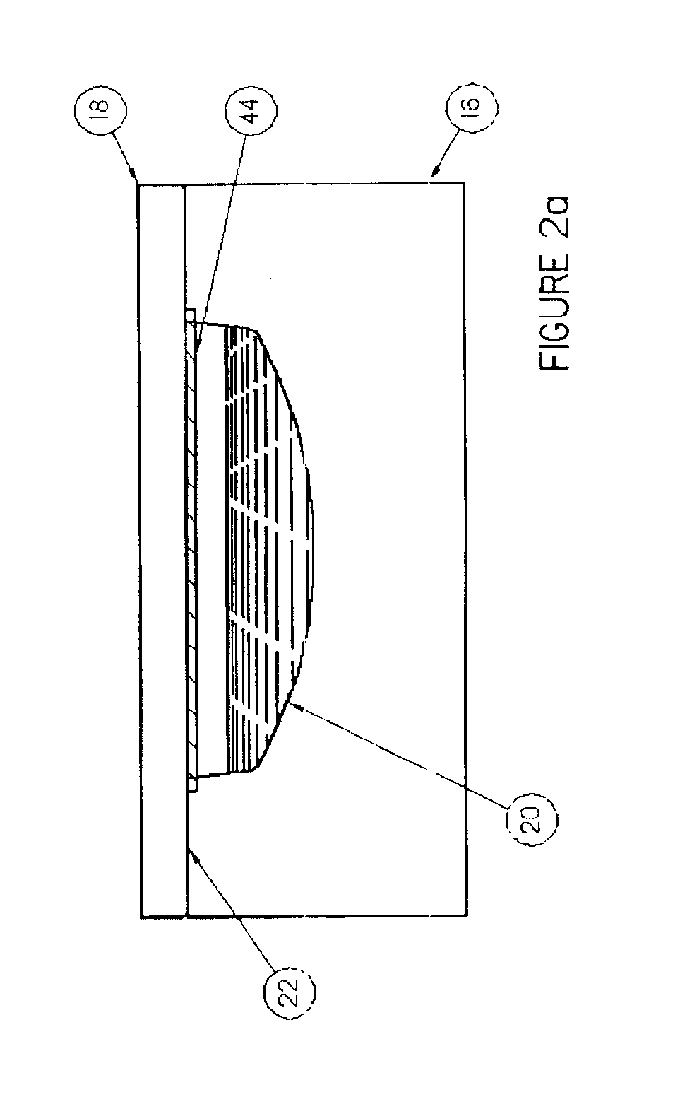
Here, the present invention uses a mold 12 configured with a cavity 14 capable of forming a plank-like raw abrading implement 15 as seen in FIGS. 2c and 4. The mold 12 includes a bottom 16 and a top 18 which include inner opposing surfaces 20 and 22, respectively, which collectively form the cavity 14. The mold 12 is relatively elongated to enable further processing of the raw implement 15 in order to provide multiple finished abrading implements 10 from the raw implement 15. The surfaces 20 and 22 can include a flat surface, an arcuate surface or a combination th...


PUM


Abstract

A method of making an abrading implement includes the steps of disposing a porous member for aiding in abrasion adjacent a first surface within a mold and supplying two reactive liquid components into the mold in a manner in which the two materials enter onto a second surface of the mold opposing the first surface, whereupon a reaction between the components form a raw implement of structural foam which is bonded to the porous member. Subsequent the reaction, the raw implement is removed from the mold and cut, preferably sawn, in a manner to provide an abrasive implement having a surface portion the foam exposed from the cut to aid in gripping the same by one's hand. An abrading implement is also provided by the method.

Description

BACKGROUND OF THE INVENTION1. Field of the InventionThe invention relates generally to the field of molding manufacturing. More particularly, but not by way of limitation, the present invention relates to improvements in abrading implements and method of making the same.2. Related ArtThere exist a variety of styles of tools for abrading, such as sanding blocks or scrubbing pads and methods of making the same. For example, sanding blocks are generally integrally formed in a mold shaped to produce a finished piece of rubber which has a pair of split ends configured with retention surfaces therein, such a plurality of nails which together are used to retain a sheet of sandpaper. The ends must be pried apart such that the nails are removed from the retention surfaces so that ends of a piece of sandpaper can be disposed between the block ends where upon release of the ends, the nails pierce the sandpaper to hold the same in place.Recent improvements in abrading implements have been made ...

Claims


Application Information

Patent Timeline
IPC IPC(8): B24D15/00B24D15/04
CPCB24D15/04
Inventor ALI, TERRYALI, CHRISTOPHERALI, PHILLIP GLENN
Owner ALI IND LLC
Learn More