Lifting restrictive signaling in a block

a technology of restrictive signaling and block, applied in the field of rails, can solve the problems of increasing costs, reducing efficiency of train operation, restricting signals in one block,

Inactive Publication Date: 2005-02-08
SIEMENS MOBILITY INC
View PDF50 Cites 97 Cited by
  • Summary
  • Abstract
  • Description
  • Claims
  • Application Information

AI Technical Summary

Benefits of technology

The present invention meets the aforementioned need to a great extent by providing a computerized train control system that uses signal information from a next block to change a restrictive signal in a block currently occupied by the train to a less restrictive signal if it can be ascertained that the condition causing the more restrictive signal has changed. This may be accomplished by receiving signal information from the next block while still in the current block and, if the signal information from the next block is no more restrictive than the signal information in the current block and if the signal for the current block is of a type that can safely be modified, allowing the train to operate as if the signal information for the current block were less restrictive than the actual, previously received signal information for the current block. In preferred embodiments of the invention, wayside signal devices transmit messages including signal information and identification information in order to allow the system to unambiguously determine that the signal information in the message corresponds to the next wayside signal device.

Problems solved by technology

However, one aspect shared by several of these systems is that a restrictive signal in one block may be caused by conditions in the next block.
A problem shared by such known systems is that there is no provision for lifting the restrictive signal in a block if conditions in the next block causing the restrictive signal “clear up.” Causing a train to operate under a restrictive signal unnecessarily makes operation of the train less efficient, which increases costs.

Method used


Image

  • Lifting restrictive signaling in a block
  • Lifting restrictive signaling in a block
  • Lifting restrictive signaling in a block

Examples


Embodiment Construction

The present invention will be discussed with reference to preferred embodiments of train control systems. Specific details, such as types of signaling systems, are set forth in order to provide a thorough understanding of the present invention. The preferred embodiments discussed herein should not be understood to limit the invention. Furthermore, for ease of understanding, certain method steps are delineated as separate steps; however, these steps should not be construed as necessarily distinct nor order dependent in their performance.

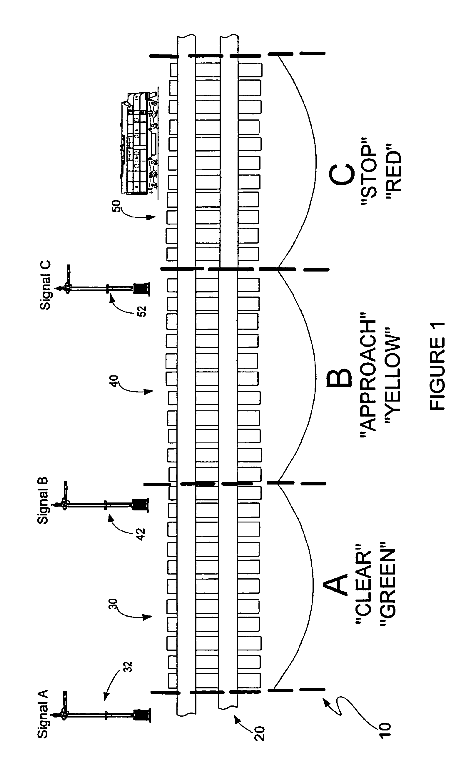
Referring now to the drawings, wherein like reference numerals designate identical or corresponding parts throughout the several views, FIG. 1 illustrates a traditional ABS system 10 in which a train track 20 that has been divided into three blocks 30, 40, 50 labeled “A,”“B” and “C,” respectively. A wayside signal 32, 42 and 52 is associated with each of the blocks 20, 40 and 50. The wayside signals 32, 42, 52 include colored lights to provide visual ...


PUM


Abstract

A train control system and method uses signal information from a next block to change a restrictive signal in a block currently occupied by the train to a less restrictive signal if it can be ascertained that the condition causing the more restrictive signal has changed. This may be accomplished by receiving signal information from the next block while still in the current block and, if the signal information from the next block is no more restrictive than the signal information in the current block, and the signal in the current block is of a type that can safely be modified, allowing the train to operate as if the signal information for the current block were less restrictive than the actual, previously received signal information for the current block.

Description

BACKGROUND OF THE INVENTION1. Field of the InventionThe invention relates to railroads generally, and more particularly to signal compliance train control methods and systems.2. Discussion of the BackgroundMany methods for controlling trains are known. Such methods include the Automated Block Signaling (ABS) and Centralized Train Control (CTC) methods. In such methods, train tracks are divided into sections, referred to in the art as blocks, and an operator is relied upon to move a train in compliance with wayside signals that are positioned some distance before a block boundary. In traditional ABS and CTC systems and the like, the wayside signals comprise colored lights that are visually observed by the operator. In more modern variants of these systems, sometimes generically referred to as communication-based train control (CBTC) systems, the signal information is transmitted into the cab of a locomotive. Examples of such systems include cab signaling systems and the TRAIN SENTINE...

Claims


Application Information

Patent Timeline
Patent Type & Authority Patents(United States)
IPC IPC(8): B61L3/12B61L23/22B61L3/00B61L23/00B61L3/22
CPCB61L3/125B61L23/22B61L3/22B61L2205/04
Inventor KANE, MARK EDWARDSHOCKLEY, JAMES FRANCISHICKENLOOPER, HARRISON THOMAS
Owner SIEMENS MOBILITY INC
Why Eureka
Try Eureka