Fluid line assembly

a technology of fluid line assembly and hose, which is applied in the direction of liquid fuel feeders, machines/engines, transportation and packaging, etc., can solve the problems of minimum bend radius, inability to convey fluid at the pressure, and high cost of flexible hoses,

Inactive Publication Date: 2005-02-15
EATON CORP
View PDF19 Cites 26 Cited by
  • Summary
  • Abstract
  • Description
  • Claims
  • Application Information

AI Technical Summary

Problems solved by technology

While flexible hoses can be easily routed and also tolerate movement and vibration better than rigid pipes, flexible hoses are generally more expensive and incapable of conveying fluid at the pressures a rigid pipe of comparable diameter can c...

Method used


Image

  • Fluid line assembly
  • Fluid line assembly
  • Fluid line assembly

Examples


Embodiment Construction

Referring now to the drawings, the preferred illustrative embodiments of the present invention are shown in detail. Although the drawings represent the some preferred embodiments of the present invention, the drawings are not necessarily to scale and certain features may be exaggerated to better illustrate and explain the present invention. Further, the embodiments set forth herein are not intended to be exhaustive or otherwise limit or restrict the invention to the precise configurations shown in the drawings and disclosed in the following detailed description.

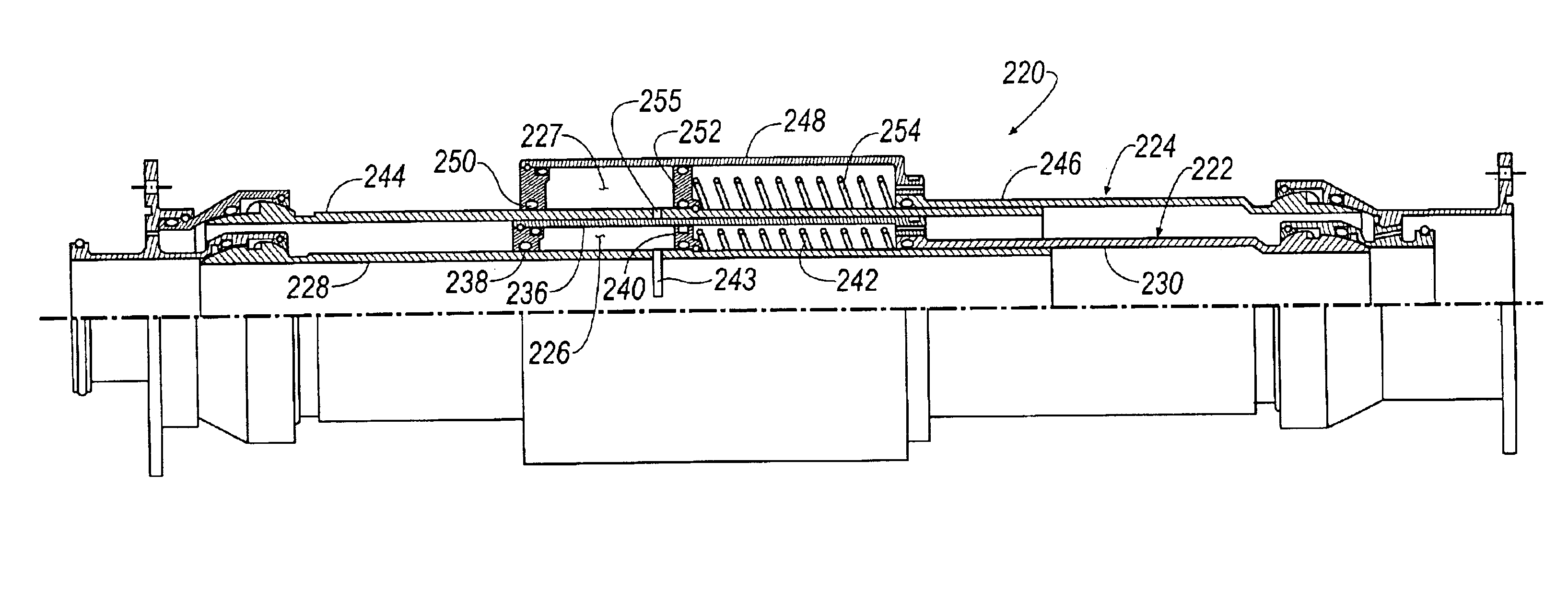
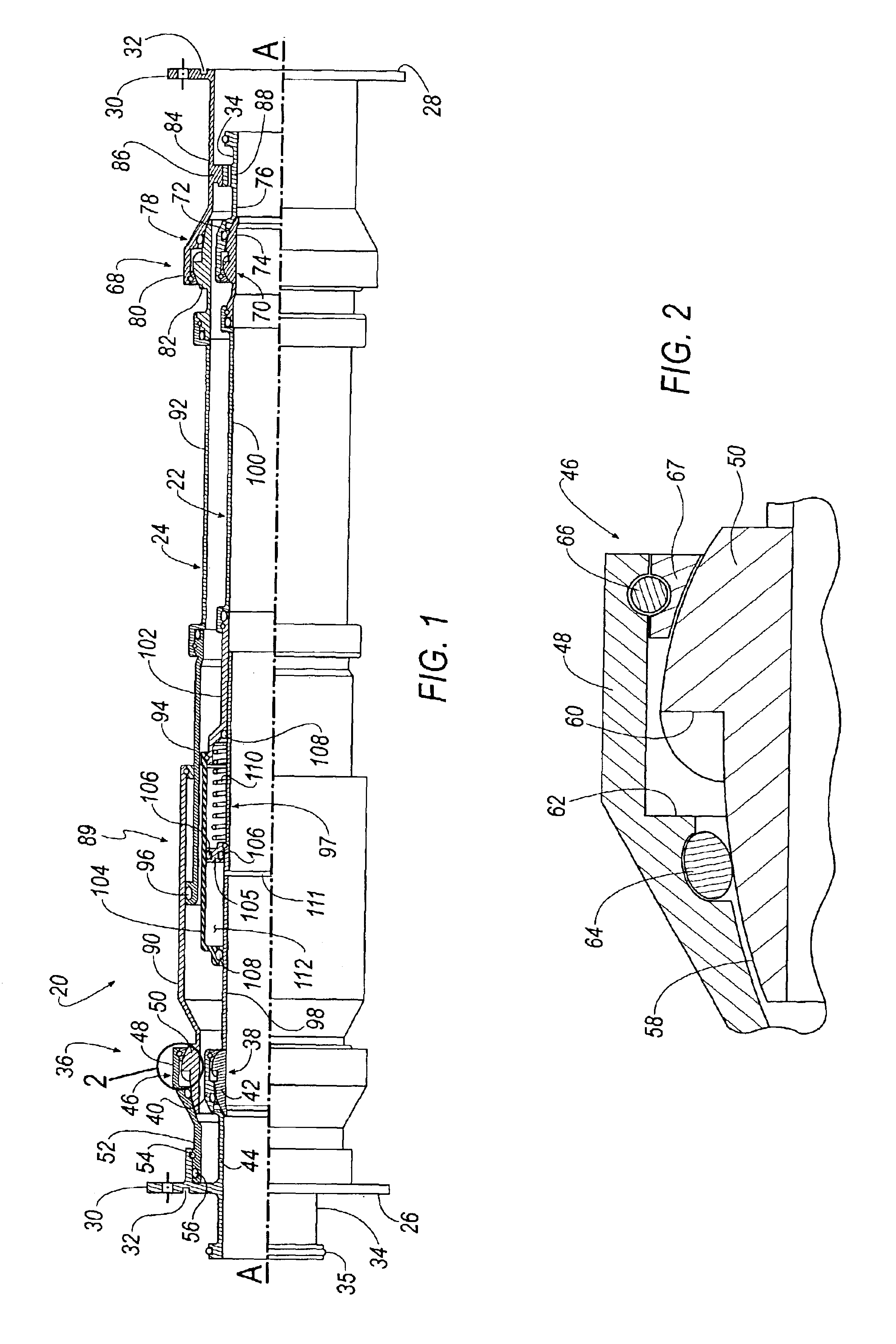
A shrouded fluid line assembly 20 according to an embodiment of the invention is shown in FIG. 1. Fluid line assembly 20 includes an inner fluid line 22 and an outer fluid line or shroud 24. Inner fluid line 22 functions as the primary fluid containment member, whereas shroud 24 functions as a secondary fluid containment member to prevent fluid leakage into the surrounding environment should inner fluid line 22 fail.

Fluid lin...


PUM


Abstract

A fluid line assembly is disclosed that includes an outer fluid line and an inner fluid line disposed substantially within the outer fluid line. The inner and outer fluid lines each include a slip joint. In an embodiment of the invention, at least one of the slip joints includes a reservoir in communication with the interior of the corresponding fluid line. Among other things, the reservoir is suitable for receiving fluid from the corresponding fluid line as the fluid line assembly is contracted and expelling fluid into the corresponding fluid line as the fluid line assembly is extended. In another embodiment of the invention, the inner and outer fluid lines include a ball joint assembly.

Description

BACKGROUND OF THE INVENTION1. Field of the InventionThe present invention relates generally to fluid transfer devices and more particularly to a shrouded fluid line assembly.2. Description of the Related ArtMany industrial, automotive and aerospace applications require the transfer of fluid between two components. For example, in certain aircraft it is common to transfer fuel between two spaced apart fuel tanks or between a fuel pump and a fuel tank. Flexible hoses and rigid pipes have generally been used to convey fluid from one component to another. While flexible hoses can be easily routed and also tolerate movement and vibration better than rigid pipes, flexible hoses are generally more expensive and incapable of conveying fluid at the pressures a rigid pipe of comparable diameter can convey. Additionally, flexible hoses generally exhibit a minimum bend radius and are not capable of more than a minimal amount of twist once installed. Moreover, both flexible hoses and rigid pipes...

Claims


Application Information

Patent Timeline
IPC IPC(8): F16L39/04F16L39/00F16L27/02F16L27/12F16L27/06F02M37/00
CPCF16L39/04F16L27/06F16L27/125F02M37/0017F02M37/0035F02M37/0088B64D37/005
Inventor CHALLENDER, GARY B.
Owner EATON CORP
Why Eureka
Try Eureka