
Protective valve cap

a protective valve and cap technology, applied in the field of protective caps, can solve the problems of dust and/or dirt on the valve, difficult to ensure that the propane in the tank has not been used, and the label to eventually degrade or fall off, so as to increase the protection from tampering, easy to remove from the valve, and easy to fit on the valve.

Inactive Publication Date: 2005-02-15
ESSENTRA PLASTICS
View PDF23 Cites 51 Cited by
  • Summary
  • Abstract
  • Description
  • Claims
  • Application Information

AI Technical Summary

Benefits of technology

Accordingly, a cap is desired that can be used on different shapes of valves and that can be tamper-evident and protective. Thus, it is an object of this invention to provide a protective cap for a valve stem that can easily fit on the valve and increase the protection from tampering, while a seal of the cap is easily broken such that the cap can be easily removed from the valve.

Problems solved by technology

With the tanks stored outside, for example, the labels are exposed to rain, snow, wind and the like, which may cause the labels to eventually degrade or fall off.
Therefore, it is difficult to make sure that the propane in the tank has not been used.
Furthermore, with such labels, if the tanks are stored outside, dust and / or dirt may build up on the valve.

Method used


Image

  • Protective valve cap
  • Protective valve cap
  • Protective valve cap

Examples


Embodiment Construction

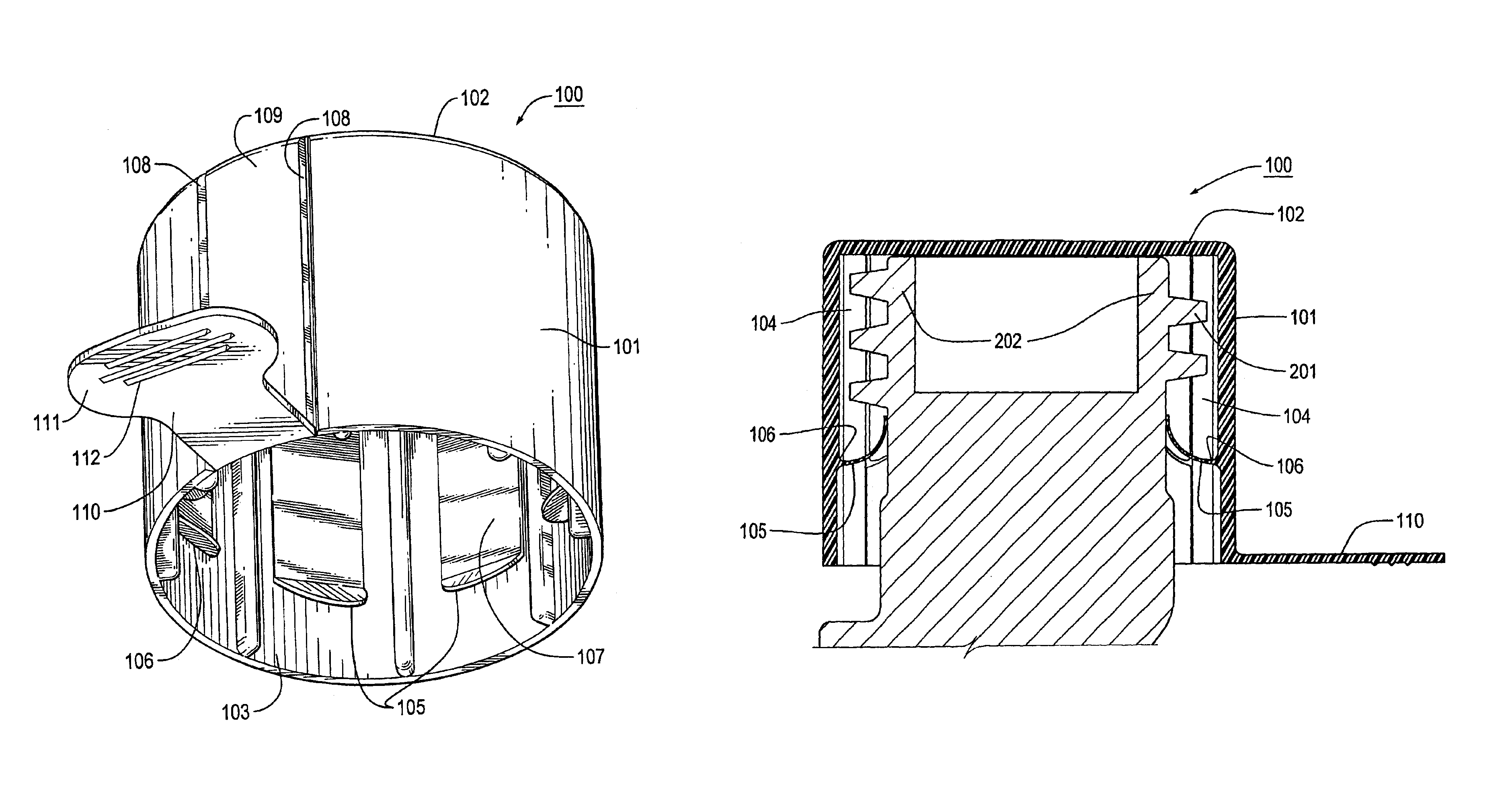
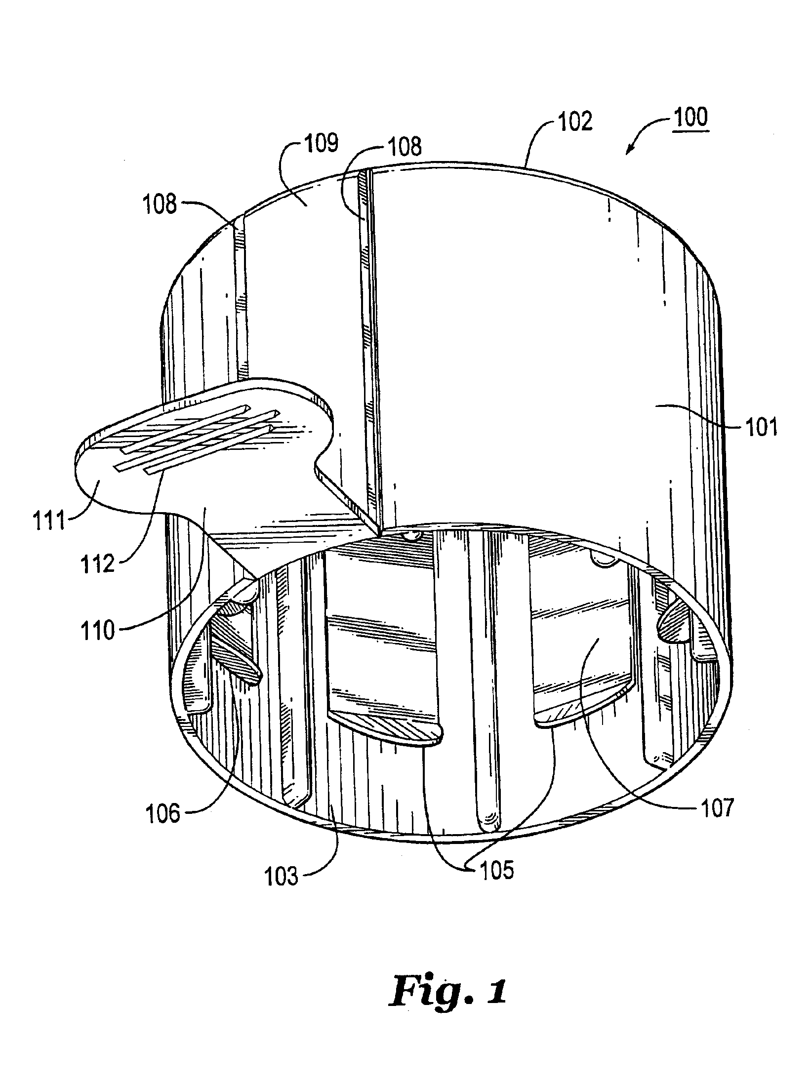
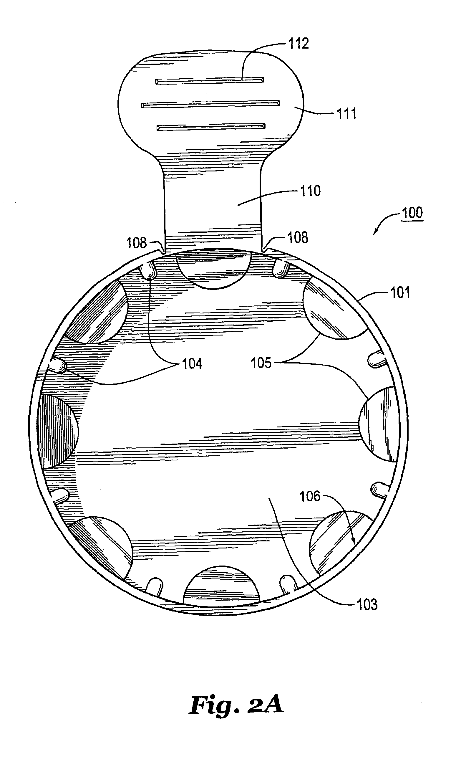
FIGS. 1, 2A, 3 and 4 show an exemplary embodiment of the protective cap according to this invention. FIGS. 2B and 2C show an alternative embodiment for a pull tab and tear strip.

As shown in FIG. 1, a protective cap 100 may be made of thermoplastic resin that is injection molded. The cap 100 has a generally cylindrical wall portion 101, a closed end 102 and an open end 103. At the closed end 102, the word “Full” or the like may be shown on an external surface to indicate that the propane tank has not been used. Also on the closed end 102, a warning message and / or safety information may be shown. The cylindrical wall portion 101 preferably has a constant diameter but other shapes are possible.

On an internal surface of the cylindrical wall portion 101, a plurality of locating ribs 104 are formed, which locate a valve 200 (see FIG. 3) to be inserted into the center of the protective cap and to distance the valve 200 from the internal surface of the protective cap as shown in FIG. 4. In ...


PUM

PropertyMeasurementUnit
flexibleaaaaaaaaaa
diameteraaaaaaaaaa
shapesaaaaaaaaaa

Abstract

A protective cap for a threaded valve stem includes a generally cylindrical portion including a closed end, an open end and a cylindrical wall portion therebetween. A plurality of locating ribs are located on an internal surface of the cylindrical wall portion. A plurality of fingers project radially inward from the internal surface between the locating ribs. A tear strip formed by two frangible members, and a pull tab are formed on an external surface of the cylindrical wall portion. Each finger is located between a pair of the locating ribs and has a flexible portion adjacent the internal surface for locating the fingers in unlocked state and a locked state. The fingers in the unlocked state are inclined toward the open end, and the fingers in the locked state curl toward the closed end.

Description

BACKGROUND OF THE INVENTION1. Field of InventionThis invention relates to a protective cap for a threaded valve stem. In particular, the application relates to a tamper resistant, easily removable, protective cap for a propane gas tank valve stem, that provides the purchaser with a convenient visual identification that the tank is full.2. Description of Related ArtConventionally, for propane valves, for example, new QCC propane valves, labels are used to indicate when a propane tank has not been used or has been filled with propane. With the tanks stored outside, for example, the labels are exposed to rain, snow, wind and the like, which may cause the labels to eventually degrade or fall off. In addition, the labels can be easily manually removed from the valve. Therefore, it is difficult to make sure that the propane in the tank has not been used. Furthermore, with such labels, if the tanks are stored outside, dust and / or dirt may build up on the valve. As such, more protection is ...

Claims


Application Information

Patent Timeline
Patent Type & Authority Patents(United States)
IPC IPC(8): B65D59/00B65D59/06
CPCB65D59/06F17C2205/05
Inventor STEFFAN, DANIEL J.
Owner ESSENTRA PLASTICS
Features
  • Generate Ideas
  • Intellectual Property
  • Life Sciences
  • Materials
  • Tech Scout
  • Unparalleled Data Quality
  • Higher Quality Content
  • 60% Fewer Hallucinations
Learn More