Medical electrical lead connector arrangement including anti-rotation means

a technology of electrical lead connectors and medical devices, which is applied in the direction of coupling contact members, coupling device connections, coupling contact members, etc., can solve the problems of non-standard connector systems, catheter inner lumens cannot accommodate standard-size lead connectors, and complicated situations. achieve the effect of reducing the axial rotation of the lead conductor

Inactive Publication Date: 2005-02-15
MEDTRONIC INC
View PDF23 Cites 101 Cited by
  • Summary
  • Abstract
  • Description
  • Claims
  • Application Information

AI Technical Summary

Problems solved by technology

The situation is complicated even further by the use of non-standard connector systems.
However, if the catheter has a small inner diameter, the inner lumen of the catheter cannot accommodate a standard-size lead connector such as one conforming to the IS-I standard.
Such slittable or splittable catheters are more expensive to manufacture, and require the additional slitting step to remove.
This non-standard connector has the drawback of necessitating the use of an even larger number of connector block configurations.
These adapters are bulky and add substantially to the size of the pocket in which the device is to be implanted.
In addition, they tend to require a number of additional steps to be performed by the physician in order to couple the leads to the implanted device, and are thus seen as generally undesirable.
Although this system allows a small-diameter lead to be used with a non-splittable catheter, this system has a disadvantage of not being adaptable for use with bipolar leads.
While this system is adaptable for use with bi-polar lead systems, it can only be used with a lead having a connector pin that is smaller than the connector bore.
That is, it is not adaptable for use with a lead having a standard connector pin size but a non-standard connector body.
In addition to the aforementioned problems, the connector pin and lead are typically fed through the connecting adapter using a pull-wire device that is screwed into a threaded recess of the connector pin's tip.
Typically, the unscrewing of the pull-wire device may cause the connector pin to axially rotate within the connector bore, and, consequently, may provide enough torque on the lead to cause the implanted electrodes to become dislodged from the patient's internal organs.
As a result of such axial rotation of the lead, and subsequent dislodging of the electrode, the implantation process of the lead and electrode would have to be performed again, thus resulting in additional time, costs, and / or trauma to the patient.

Method used


Image

  • Medical electrical lead connector arrangement including anti-rotation means
  • Medical electrical lead connector arrangement including anti-rotation means
  • Medical electrical lead connector arrangement including anti-rotation means

Examples


Embodiment Construction

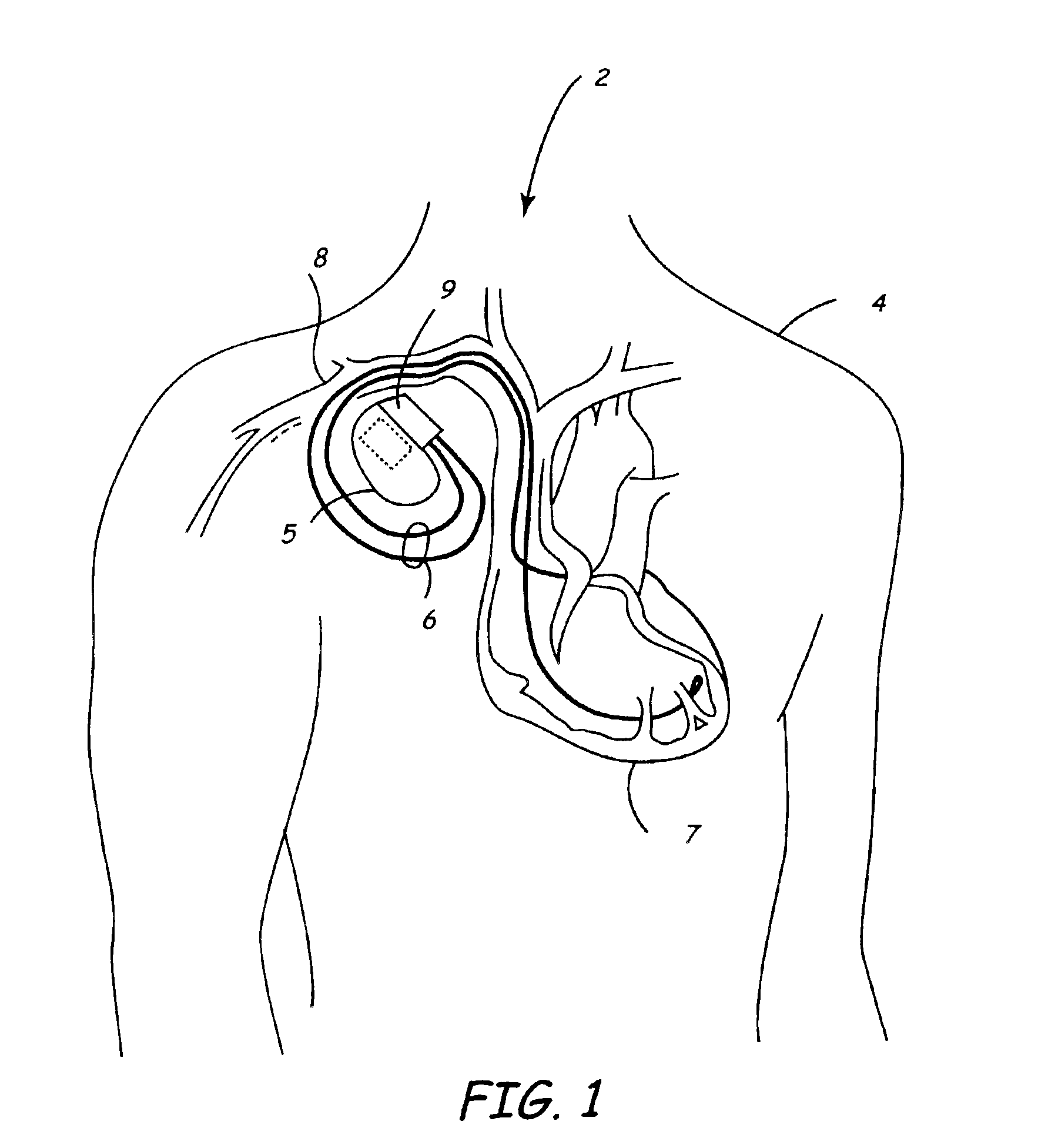
Turning now to the drawings, and specifically referring to FIG. 1A, an implantable medical device (IMD) system 2 that includes an implantable medical device 5 is provided. In accordance with one embodiment, the implantable medical device 5 may take the form of a pacemaker, cardioverter, defibrillator, neural stimulator, or drug administering device that has been implanted within a patient's body 4. It will be appreciated that the implantable medical device 5 may take the form of various other medical devices, and, thus, need not necessarily be limited to the aforementioned examples.

The implantable device 5 is housed within a hermetically sealed, biologically inert outer container or housing, which may itself be conductive so as to serve as an electrode in the pacemaker's pacing / sensing circuit. One or more pacemaker leads, collectively identified with reference numeral 6 in FIG. 1A, are electrically coupled to the implantable device 5 and extend into the patient's heart 7 via a vein...


PUM


Abstract

A lead connector arrangement includes a non-cylindrically shaped connector pin coupled to a lead conductor and a connector sleeve assembly for receiving the non-cylindrically shaped connector pin. The connector sleeve assembly includes an insert with an axial bore formed therein that complements the shape of the non-cylindrical connector pin. According to one embodiment, the non-cylindrical connector pin may be provided in the form of a triangular, square, rectangular, or hexagonal shape. The axial bore has a complimentary shape to receive the connector pin. When the connector pin is threaded through the connector sleeve assembly using a pull-wire device, the pull-wire device may be unscrewed from the connector pin without causing axial rotation of the lead conductor when the connector pin is fully inserted within the axial bore.

Description

BACKGROUND OF THE INVENTIONThe present invention relates generally to mechanisms for interconnecting electrical leads and electrical medical devices; and more particularly, to systems and methods of interconnecting implantable electrical leads and implantable medical electrical devices such as pacemakers, nerve stimulators, implantable defibrillators, implantable monitors, and so forth.DESCRIPTION OF THE RELATED ARTAs implantable electrical devices have increased in their complexity, there has been an increasing variety of electrical lead systems developed for use in conjunction with these devices. Nowhere is this more apparent than in the context of implantable cardioverter / defibrillators, which may include three, four, five, or more electrodes located on various numbers of implantable electrical leads. The leads themselves may carry one, two, three, or more electrodes, and may employ a variety of different electrical connector configurations and types. As a result, manufacturers o...

Claims


Application Information

Patent Timeline
Patent Type & Authority Patents(United States)
IPC IPC(8): A61N1/375A61N1/05A61N1/372H01R24/04H01R24/00H01R31/06H01R13/52A61N1/02H01R24/58H01R43/00
CPCA61N1/056A61N1/3752H01R24/58H01R31/06A61N1/0573A61N2001/0578H01R2201/12H01R13/5224H01R2107/00A61N2001/0585
Inventor STEIN, PAUL M.HOLLEMAN, TIMOTHY W.RIES, ANDREW J.SCHRODER, HARRYHONECK, JORDON D.SOMMER, JOHN L.BJORKLUND, VICKI L.
Owner MEDTRONIC INC
Why Eureka
Try Eureka