Safety needle assembly

a needle and safety technology, applied in the field of safety needle assembly, can solve the problems of sharp end of the needle cannula, potential injury risk, and disclosure of the safety needle assembly

Inactive Publication Date: 2005-02-15
NOVO NORDISK AS
View PDF7 Cites 277 Cited by
  • Summary
  • Abstract
  • Description
  • Claims
  • Application Information

AI Technical Summary

Benefits of technology

[0011]It is further an objective of the present invention to provide a safety needle assembly having a spring with only a limited force thereby offering the user maximum comfort.
[0013]When the locking element is provided as a separate element located between the spring and the shield and moved simultaneously with the shield, the locking protrusion can be guided during the longitudinal movement of the locking member thereby eliminating the need for tracks or cams thus making it possible to construct the safety needle assembly from only three plastic part in addition to the hub.
[0014]Since there are no tracks or cams as such the internal tolerances are not that important, and the friction can be kept rather low which renders it possible to utilize a somewhat soft spring, which enhances the user comfort.
[0019]The guiding means for guiding the locking protrusion comprises only horizontally difined ribs and fins as specified in claim 6. This makes both the moulding of the parts and the assembly of the parts very simple.
[0022]By providing the housing with a window through which the locking protrusion can be viewed when it is in the arrested position, it is ensured that a user can visible inspect whether the safety needle assembly has been used before or not.

Problems solved by technology

The problem presented by the disposal of a needle assembly, and indeed, by any handling of the needle assembly, is the potential risk of being injured by the sharp end of the needle cannula.
This is particular dangerous when following after the penetration of a patients skin since the needle cannula then may be contaminated and therefore capable of spreading diseases such as hepatitis and HIV.
The safety needle assembly disclosed in WO 01.76665 is however rather cumbersome and consist of a large number of parts that must be moulded and afterwards fitted together very precisely in order to obtain the correct movement of the cam follower.
It is also a fact that the different plastic parts of an assembled construction have a tendency to change the relative dimensions when the construction is sterilized using steam or gas.
This is an inconvenience for the user, since the user has to press the protective cap in the proximal direction literally with the use of his or hers skin while making the injection.

Method used


Image

  • Safety needle assembly
  • Safety needle assembly
  • Safety needle assembly

Examples


Embodiment Construction

[0010]It is henceforth an object of the present invention to provide a safety needle assembly, which overcomes the inconveniences of the prior art safety needle assemblies, and especial to provide a safety needle assembly which is made from fewer parts, and which parts are not subject to very strict tolerances.

[0011]It is further an objective of the present invention to provide a safety needle assembly having a spring with only a limited force thereby offering the user maximum comfort.

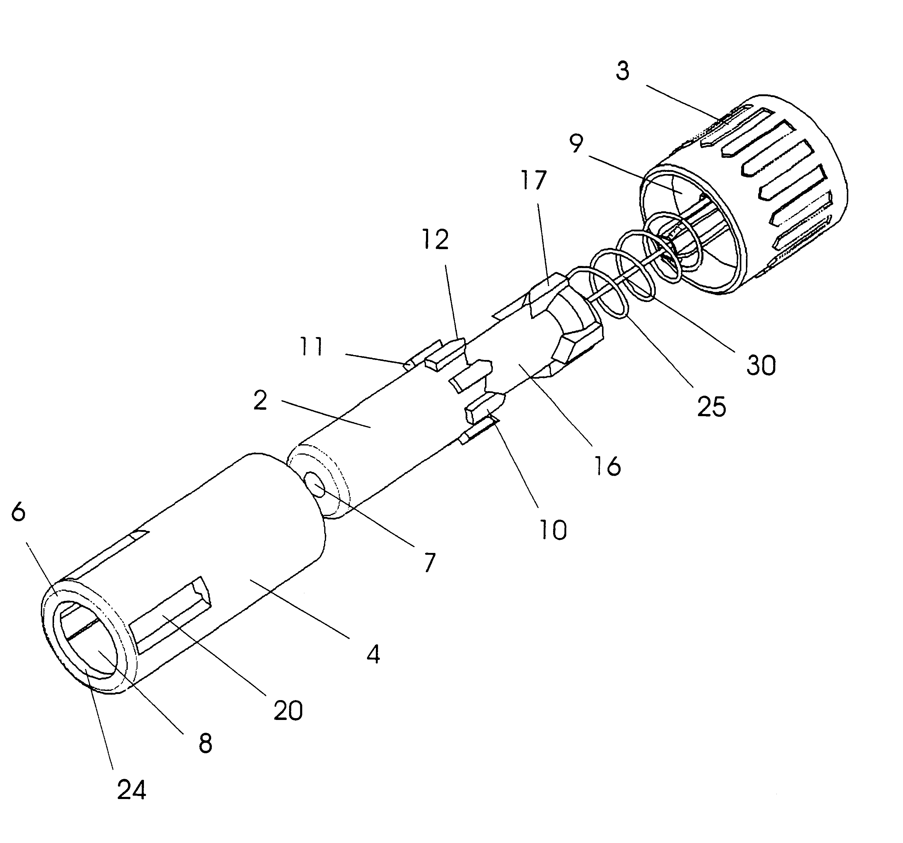
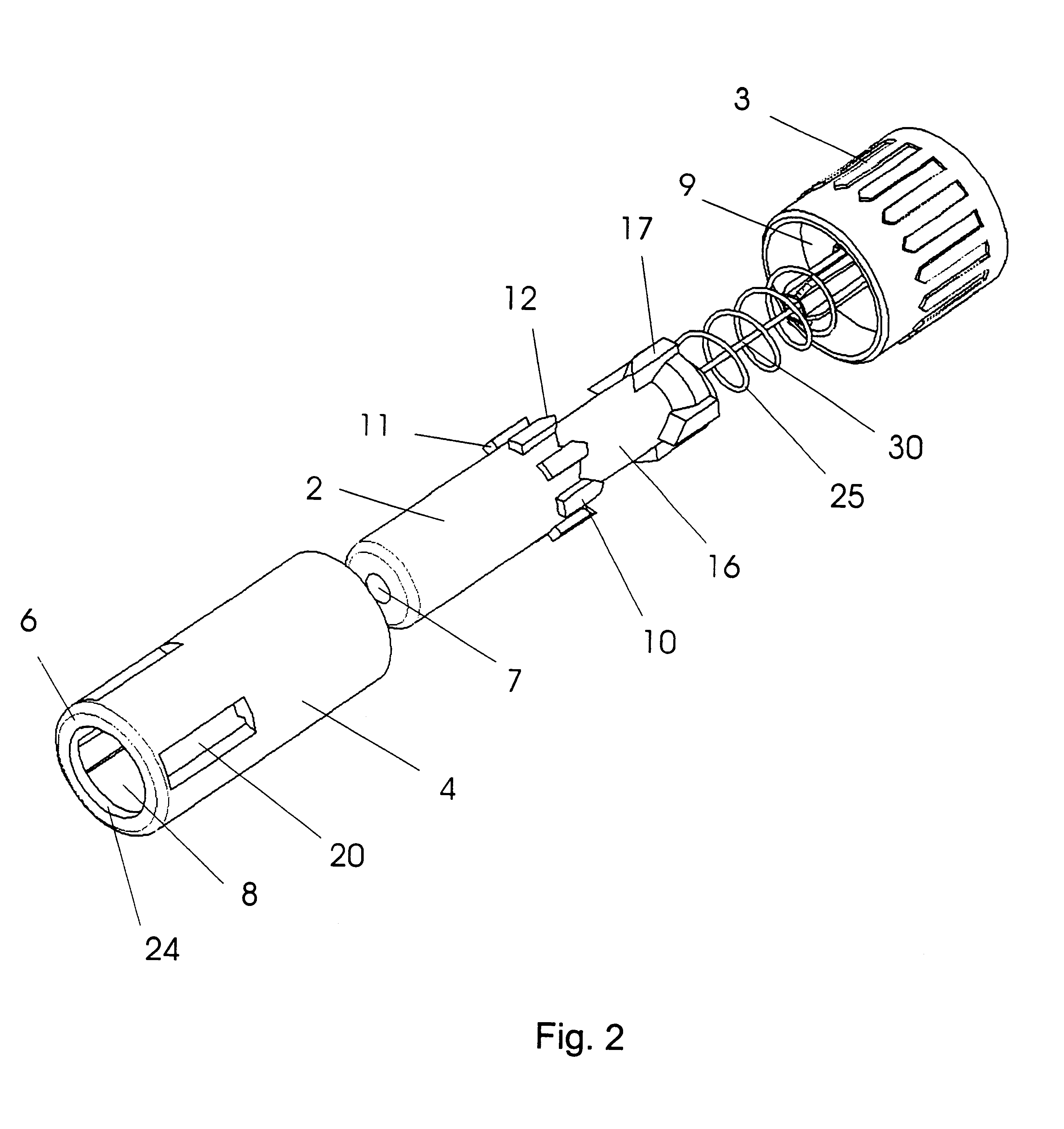
[0012]In order to overcome the drawbacks of the prior art it is suggested to provide the safety needle assembly with a separate locking element located between the spring and the shield according to claim 1.

[0013]When the locking element is provided as a separate element located between the spring and the shield and moved simultaneously with the shield, the locking protrusion can be guided during the longitudinal movement of the locking member thereby eliminating the need for tracks or cams thus making...


PUM


Abstract

The invention relates to a safety needle assembly for injecting a fluid into a human body comprising a cylindrical housing with a bottom surface supporting a needle cannula and a shield telescopically movable relative to the housing. A spring located within the housing urges the shield in a distal needle covering direction and a locking member also provided inside the housing moves simultaneously with the shield during injection and automatically locks the shield in a position where the sharp end of the needle cannula is concealed thereby irreversible immobilizing the safety needle assembly.

Description

CROSS REFERENCE TO RELATED APPLICATIONS[0002]This application claims the benefit of priority of U.S. provisional application No. 60 / 343,045, filed Dec. 22, 2001 and Danish Application PA 2001 01772, filed Nov. 30, 2001; the contents of both are hereby incorporated by reference in their entirety.FIELD OF THE INVENTION[0003]The invention relates to a safety needle assembly, which reduces the risk of accidental needle-stick injuries, and especially a safety needle assembly where a needle cannula is mounted in a hub.Description of Related Art[0004]Needle assemblies are commonly used to either inject substances into or extract substances out of human or animal bodies. Such needle assemblies are typically disposable and are discarded after only one use. The problem presented by the disposal of a needle assembly, and indeed, by any handling of the needle assembly, is the potential risk of being injured by the sharp end of the needle cannula. This is particular dangerous when following afte...

Claims


Application Information

Patent Timeline
Patent Type & Authority Patents(United States)
IPC IPC(8): A61M5/00A61M5/32B42D15/00G09F1/04
CPCA61M5/002A61M5/326A61M5/3271A61M2005/3247A61M2005/3267A61M2205/6063B42D15/00G09F1/04A61M2205/584A61M5/32A61M5/178A61M5/34A61M5/3245
Inventor JENSEN, KARSTENNYMARK, NIELS
Owner NOVO NORDISK AS
Why Eureka
Try Eureka