
Tire condition monitoring system with improved sensor means

a technology of condition monitoring and sensors, applied in the field of system having an improved sensor means, can solve the problems of inconvenient use for users and less attractive use of such sensors

Inactive Publication Date: 2005-02-15
SMITH JULIAN +3
View PDF6 Cites 53 Cited by
  • Summary
  • Abstract
  • Description
  • Claims
  • Application Information

AI Technical Summary

Benefits of technology

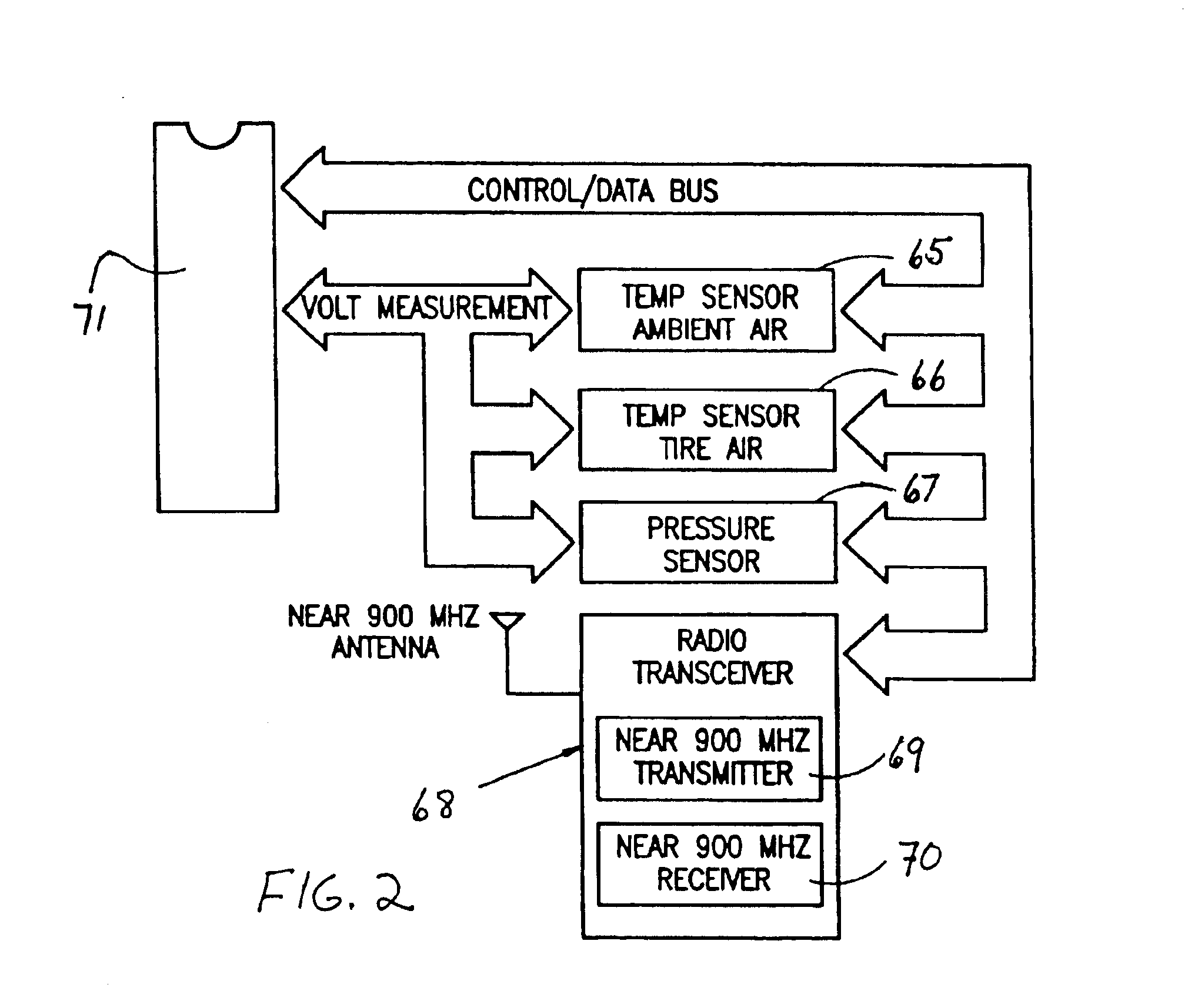
"The present invention provides a sensor for adjusting the pressure of a tire that can be easily installed and removed without replacing the sensor each time the pressure is adjusted. The sensor includes a housing with a closed chamber and two openings, an abutment for depressing the valve stem, a valve for controlling the air pressure, and a sensing mechanism for measuring the pressure within the chamber. The sensor also has a transmitter for sending the sensed pressure data to a control unit. The device can also include additional sensors for measuring ambient pressure and temperature, a battery for powering the sensors, processor, and transmitter, and a transmitter / receiver for activating, deactivating, and querying the device."

Problems solved by technology

Although such sensors have been highly effective in sensing pressure and temperature conditions when mounted on the valve stems of tires, and transmitting data signals corresponding to such conditions to the control unit, they present an obstacle when seeking to connect a compressed air line to the valve stems of the tires for adjusting the pressures of the having to remove and replace each sensor.
Such requirement of removal and replacement of such sensors each time the inflation pressure of the tire is adjusted has been found to be an inconvenience to the user which renders the use of such sensors less attractive.

Method used


Image

  • Tire condition monitoring system with improved sensor means
  • Tire condition monitoring system with improved sensor means
  • Tire condition monitoring system with improved sensor means

Examples


Embodiment Construction

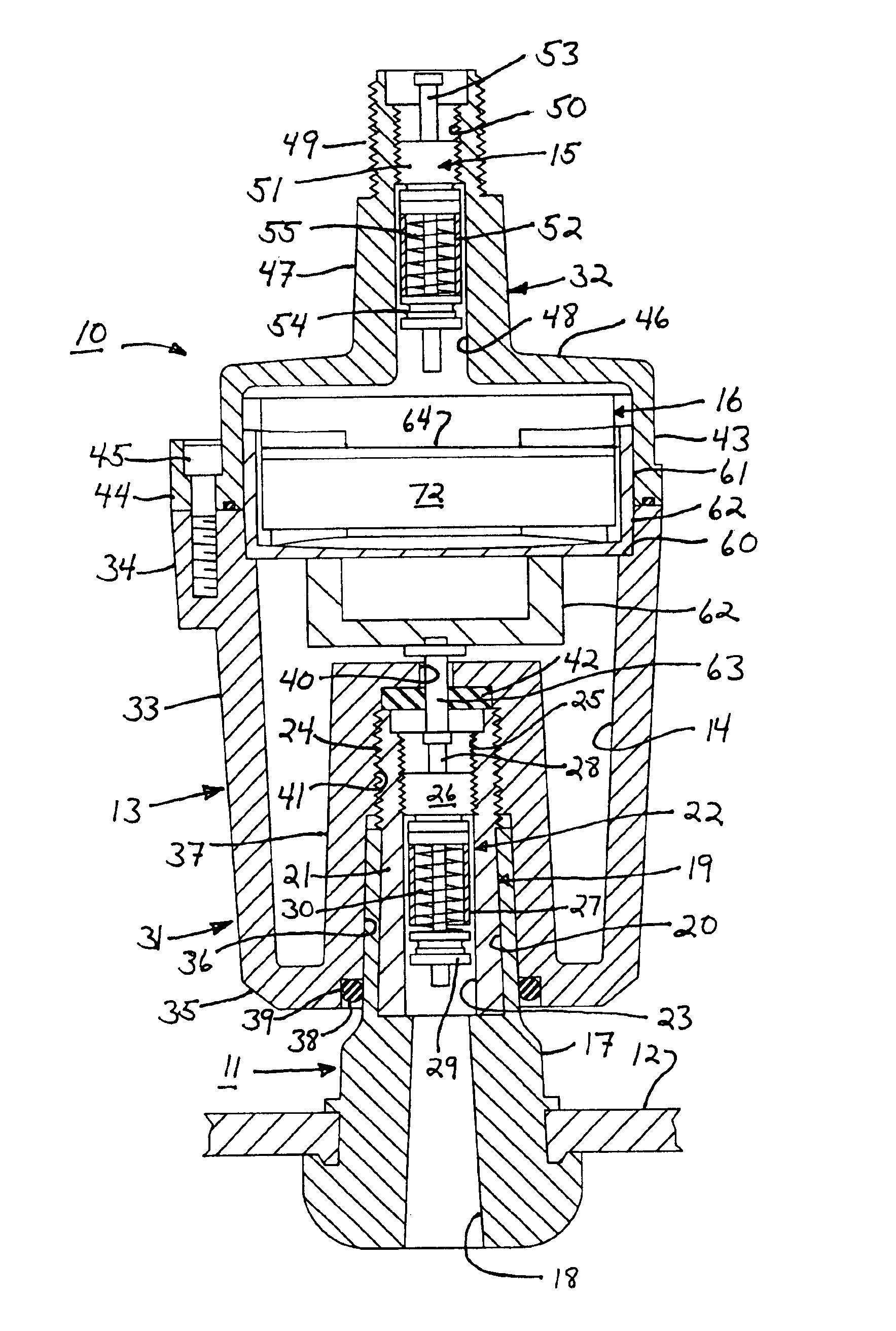
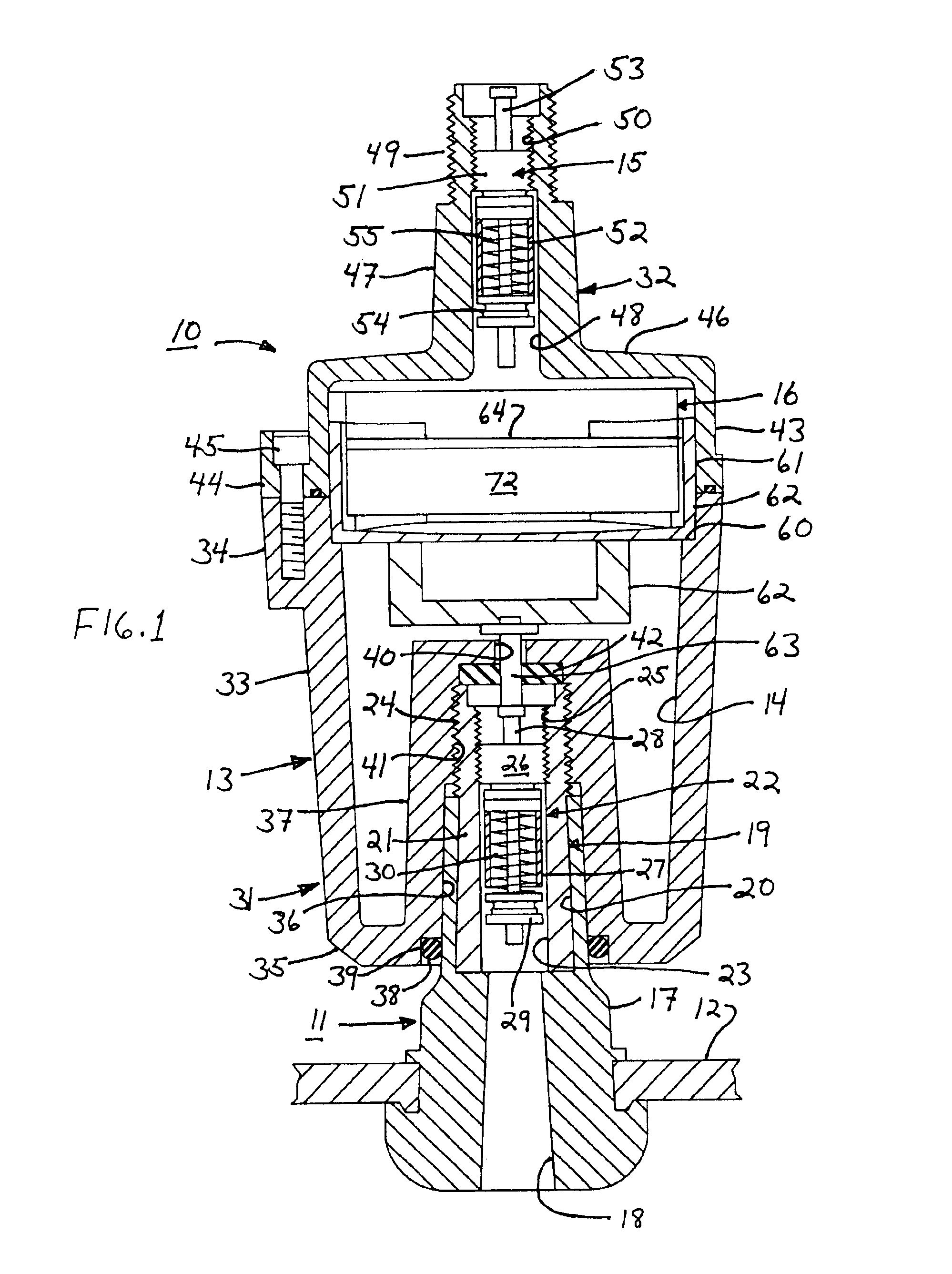
Referring to the drawings, there is illustrated a system for monitoring certain conditions of an inflatable tire of a vehicle which generally consists of at least one sensor device 10 mountable on a valve stem 11 of a tire 12 and a control unit 79 which may be either mountable on the vehicle or detached for use as a portable unit. The sensor device includes a housing 13 defining a chamber 14, a valve 15 and electronics module 16. Valve stem 11 is of a conventional construction consisting of an elongated body member 17 having a longitudinal bore 18 therethrough and a valve core 19 disposed in an enlarged section 20 of bore 18. Valve core 19 includes a substantially cylindrical body member 21 seated in enlarged section 20 and a valve 22 disposed in a longitudinal bore 23 therein. The free end of cylindrical body member 21 is provided with a set of exterior threads 24 and a set of interior threads 25.

Valve core 19 is of a conventional construction found in most valve stems and includes...


PUM


Abstract

A sensor device mountable on a threaded valve stem of an inflatable tire of a vehicle having an actuating pin adapted to be depressed by a component of an air gauge or a connecting fixture of a compressed air line, generally consisting of a housing defining a closed chamber, having a first threaded opening permitting such housing to be threaded onto the valve stem, and a second opening; an abutment pin disposed in the housing engageable with the actuating pin of the valve stem for depressing the actuating pin of the valve stem and thereby opening the valve stem when the housing is threaded onto the valve stem, providing an intercommunication of the interiors of the tire and the housing; a valve disposed in the second opening of the housing having an actuating pin adapted to be depressed by the component of an air gauge or connecting fixture of a compressed air line; a sensor mounted in the housing for sensing the pressure in the housing chamber; a microcontroller connected to the pressure sensor for receiving and processing signals therefrom corresponding to sensed pressures; and a transmitter mounted on the housing and coupled to the processor for transmitting processed signals corresponding to sensed pressures.

Description

FIELD OF THE INVENTIONThis invention relates to a system for monitoring certain conditions of inflated tires of vehicles, and more particularly to such a system having an improved sensor means.BACKGROUND OF THE INVENTIONIn U.S. Pat. No. 6,034,596, incorporated herein by reference, there is disclosed a system for monitoring the pressure and temperature of the tires of a vehicle which generally consists of a set of sensors mountable on the valve stems of the vehicle tires, and a control unit mounted on the vehicle, provided with means for transmitting signals between the control unit and the sensors. Each of such sensors generally includes a housing having a threaded opening, adapted to be threaded onto a tire valve stem to thereby intercommunicate the interior of the tire with the interior of the housing, and pressure and temperature sensors, a microcontroller, a transmitter / receiver and a power supply mounted within such housing. Such system operates in a manner whereby the control ...

Claims


Application Information

Patent Timeline
Patent Type & Authority Patents(United States)
IPC IPC(8): B60C23/04B60C23/02
CPCB60C23/0496B60C23/0408
Inventor SMITH, JULIANHOLMBRAKER, STEVENCAMPBELL, III, WILLIAMBARTLETT, ARLIN
Owner SMITH JULIAN
Learn More