
Spring and apparatus for its use

a technology of spring and apparatus, applied in the direction of hose connection, machine/engine, coupling, etc., can solve the problems of damage to vital aircraft components, vibration in the exhaust system, and stress cracking in the walls of the exhaust system

Inactive Publication Date: 2005-02-22
ASHLOCK JERRY L
View PDF31 Cites 7 Cited by
  • Summary
  • Abstract
  • Description
  • Claims
  • Application Information

AI Technical Summary

Benefits of technology

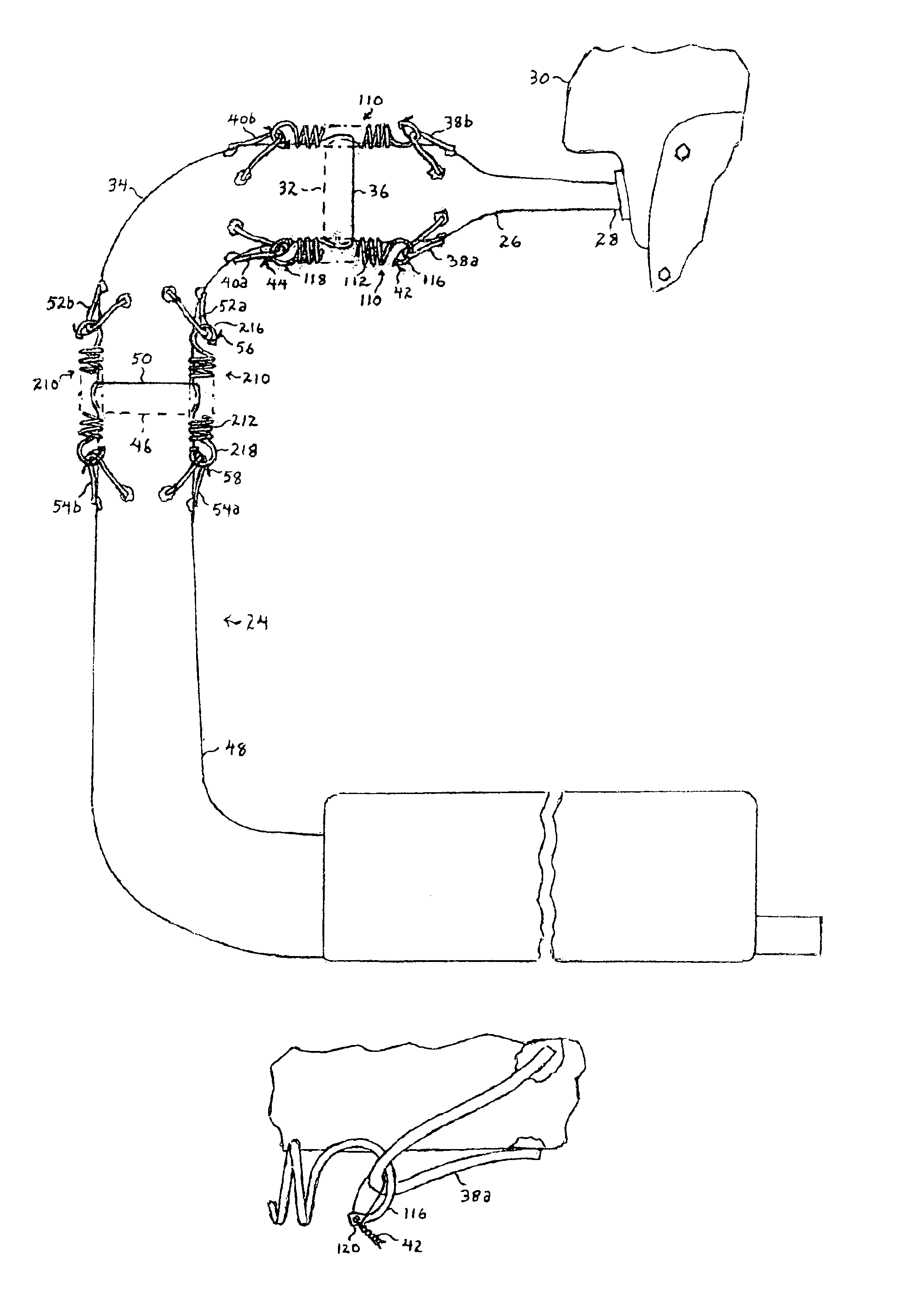
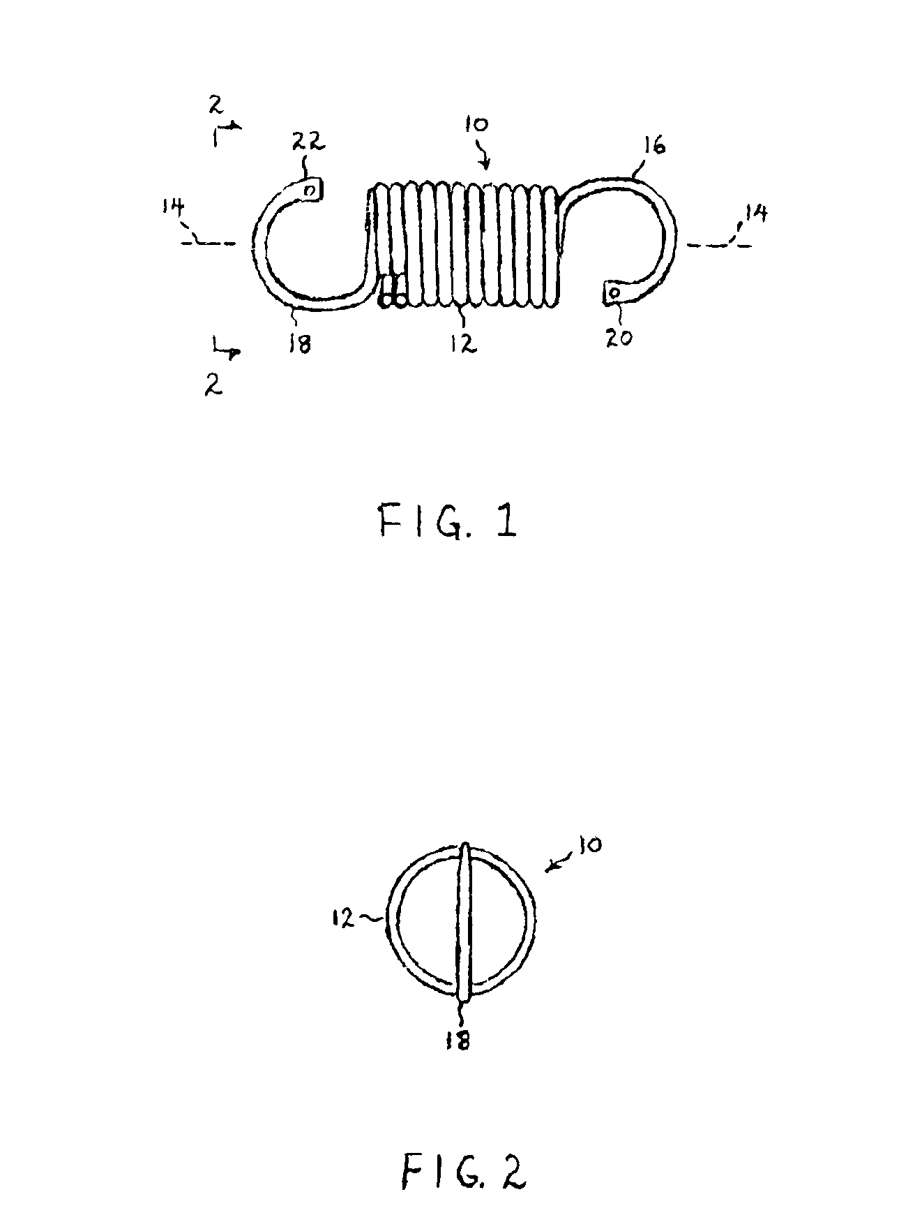
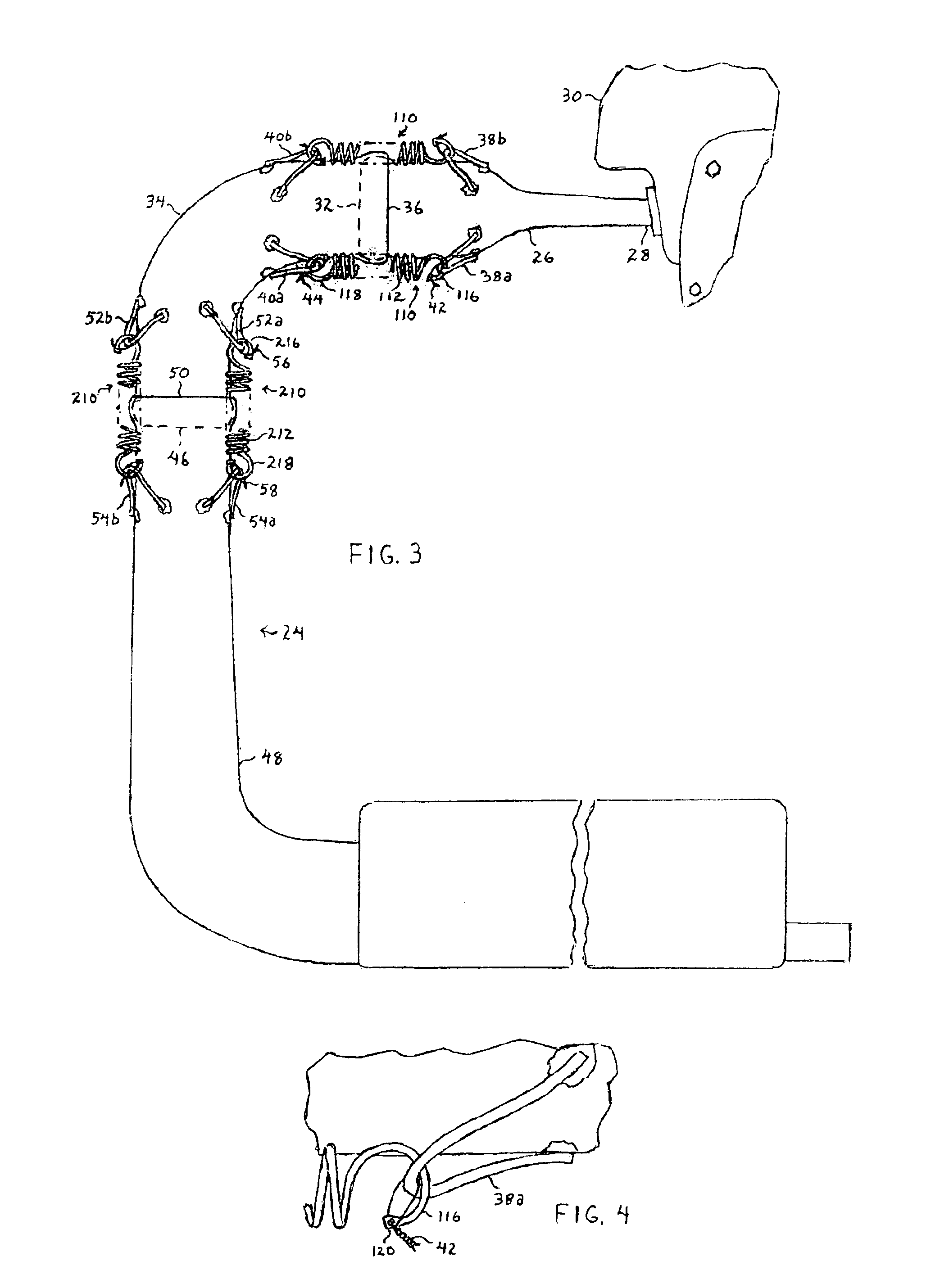
Therefore, the novel spring of the invention, having hook ends with holes therethrough, enables such ends to be secured with safety wire to respective hook retaining members formed as loops. As will be explained further below with respect to an aircraft having an uncovered and exposed exhaust system, the spring safety wired to loops in the manner described above effectively prevents any part of the spring (including the end of a hook) or loop from impacting and damaging a vital component (i.e. propeller) of the aircraft upon breakage of the spring or loop.

Problems solved by technology

An exhaust system can be very susceptible to vibration from an engine, such as in an ultralight aircraft.
If the exhaust system is constructed as a unitary welded structure, the walls of the exhaust system are very susceptible to stress cracking.
In an ultralight aircraft having its engine and exhaust system uncovered and exposed, breakage of a spring or loop can result in damage to vital aircraft components.
In an aircraft (i.e. powered parachute) with a pusher propeller positioned to the rear of the engine and exhaust system, a broken spring, or a broken loop and the spring, can fly into and damage the propeller.
Aside from the cost of replacing the damaged propeller, a portion of a propeller blade could be lost in flight and result in severe vibration, which can then lead to damage to the remainder of the propeller as well as the engine or gear box.

Method used


Image

  • Spring and apparatus for its use
  • Spring and apparatus for its use
  • Spring and apparatus for its use

Examples


Embodiment Construction

Referring to FIG. 1, spring 10 is comprised of a wire (i.e. of a high carbon spring steel) which includes an elastic, coiled central portion 12 having a longitudinal axis 14. Coiled central portion 12 is preferably helically wound so as to have multiple and adjacent convolutions that contact one another when the coiled central portion is in its relaxed state as shown. Spring 10 further includes opposing end portions formed as hooks 16 and 18. Hook 16 terminates in an end 20 having a hole therethrough, and hook 18 similarly terminates in an end 22 also having a hole therethrough. Each of hooks 16 and 18 is curved so as terminate in its corresponding end adjacent to but longitudinally spaced from coiled central portion 12. As shown with respect to two convolutions of coiled central portion 12 that are partially broken away, the wire of spring 10 is preferably round in cross section, except for ends 20 and 22 which are flattened. Each flattened end and the remainder of the correspondin...


PUM


Abstract

There is provided a spring comprised of a wire which includes an elastic, coiled central portion and opposing end portions formed as hooks. Each hook terminates in an end having a hole therethrough. The spring is useful with an exhaust system of the type having a pair of sections joined but not affixed to one another to thereby form a flexible joint. A loop is fixedly connected to each section adjacent to the joint. The opposing hooks of the spring are securely received by the loops, and a safety wire is received through the hole in the end of each hook and secured to the corresponding loop. In an aircraft having an exposed exhaust system, the safety wire prevents a broken spring or loop from impacting and damaging vital components of the aircraft, particularly a pusher propeller positioned to the rear of the exhaust system.

Description

BACKGROUND OF THE INVENTIONThe invention relates to a spring and an apparatus for its use with an exhaust system.An exhaust system can be very susceptible to vibration from an engine, such as in an ultralight aircraft. If the exhaust system is constructed as a unitary welded structure, the walls of the exhaust system are very susceptible to stress cracking. This problem is solved by constructing the exhaust system from at least two, and most preferably three, sections that are flexibly joined to one another. The sections are connected with ball joints that are held together with springs, thereby allowing relative movement between the joined sections. Adjoining sections have metal loops welded thereto for securely receiving opposing hooks of each spring.In an ultralight aircraft having its engine and exhaust system uncovered and exposed, breakage of a spring or loop can result in damage to vital aircraft components. In an aircraft (i.e. powered parachute) with a pusher propeller posi...

Claims


Application Information

Patent Timeline
Patent Type & Authority Patents(United States)
IPC IPC(8): F16L21/08
CPCF01N13/1811F16L21/08F01N2590/00
Inventor ASHLOCK, JERRY L.
Owner ASHLOCK JERRY L
Learn More