
High performance light engine

a light engine and high-performance technology, applied in the field of optical systems, can solve the problems of poor color performance, short usage life, poor intensity of traditional illumination lamps,

Inactive Publication Date: 2005-02-22
INNOVATIONS & OPTICS
View PDF11 Cites 18 Cited by
  • Summary
  • Abstract
  • Description
  • Claims
  • Application Information

AI Technical Summary

Problems solved by technology

Traditional illumination lamps suffer from poor color performance, poor intensity, and / or short usage life.
In addition, tungsten filament lamps generate an enormous amount of heat, normally between 100 to 300 watts of heat energy, which results in raising the temperature of the surrounding environment.
Also, tungsten filament lamps have a low electrical to optical efficiency and, thus, require large amounts of electrical power to generate a high intensity illumination power.
Finally, tungsten lamps have a low life span, usually operating for about 500 hours.
However, metal halide arc lamps cannot be used in many applications because they cannot be hot-striked.
That is, they cannot be cycled off and on without a significant restart time.
A metal halide arc lamp that is cycled off then back on will not only fail but will also usually be damaged.
More recent metal halide arc lamps have a much quicker on-off-on cycle time, however, they have low intensity illumination pattern.

Method used


Image

  • High performance light engine
  • High performance light engine
  • High performance light engine

Examples


Embodiment Construction

Referring to the drawings and in particular to FIGS. 1-10, there is shown the preferred embodiments of the invention.

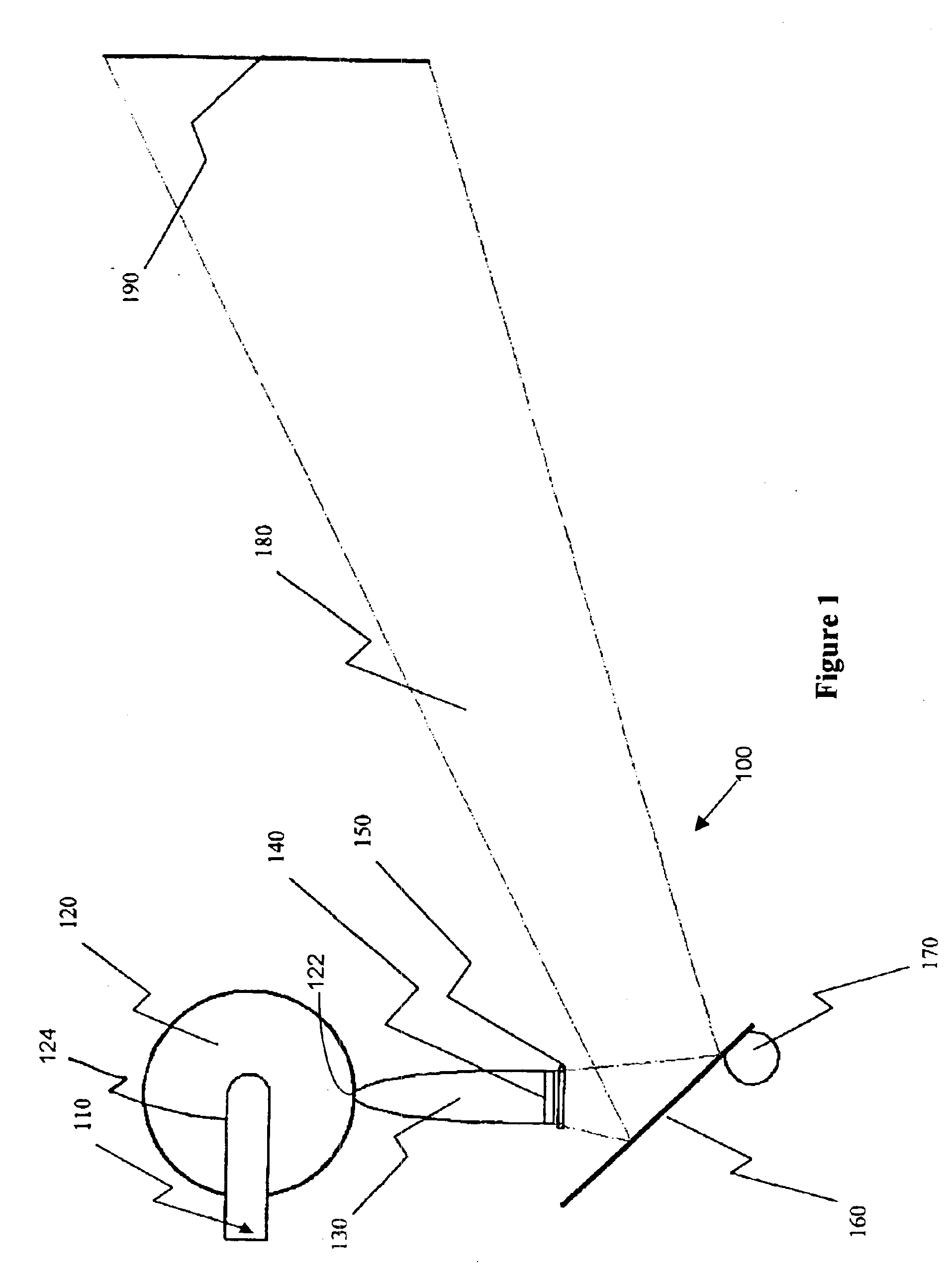
FIG. 1 illustrates optical system 100 according to a preferred embodiment of the invention. The optical system 100 includes a light source 110, an integrating cavity 120, a concentrator 130, an optical filter 140, an intensity controller 150, a reflector 160, an illumination pattern controller 170, an illumination region 180, and an illumination pattern 190.

The light source 110 is optically attached to the integrating cavity 120 and emits optical energy which is captured by the integrating cavity 120. In a preferred embodiment of the invention, the light source is a high performance, high power, metal halide arc lamp. In an alternative embodiment, any light source that can provide sufficient optical energy to satisfy the requirements of the illumination pattern may be used.

In an alternative embodiment, the optical source includes a three lamp cluster where only one la...


PUM


Abstract

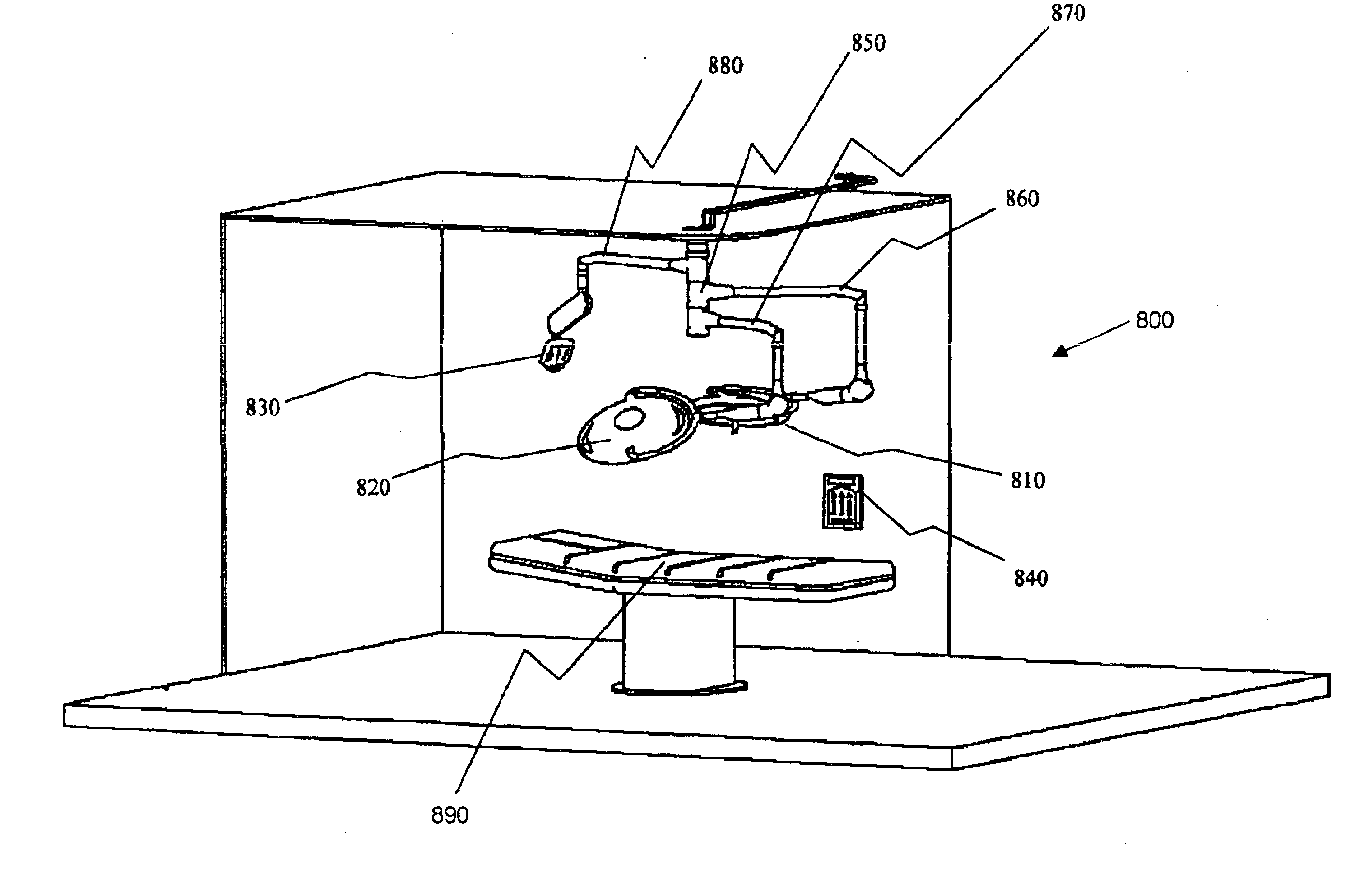
A surgical lighting system including overhead surgical lights having integrating cavities which capture metal halide arc lamp optical energy and output spatially uniform optical energy to reflectors which direct the optic energy to a common surgical illumination region, a surgical light port system having illuminating ports, and a thermal dissipater. The surgical lighting system includes power back-up systems and light sources with multiple lamps that are automatically sequenced to provide constant surgical illumination.

Description

CROSS-REFERENCE TO RELATED APPLICATIONSFIELD OF THE INVENTIONThis invention relates to an optical system, and more particularly, to an optical system that provides constant white light to a region.BACKGROUND OF THE INVENTIONTraditional illumination lamps suffer from poor color performance, poor intensity, and / or short usage life. Tungsten filament lamps, for example, while providing high intensity in the illumination pattern, emit a spectral distribution that is yellowish to the human visual system. In addition, tungsten filament lamps generate an enormous amount of heat, normally between 100 to 300 watts of heat energy, which results in raising the temperature of the surrounding environment.Also, tungsten filament lamps have a low electrical to optical efficiency and, thus, require large amounts of electrical power to generate a high intensity illumination power. The higher amount of electrical power also contributes to the higher amount of heat generated by the tungsten filament l...

Claims


Application Information

Patent Timeline
IPC IPC(8): F21V29/02F21V29/00F21V19/04F21S8/00F21V14/04F21V14/00F21V9/04F21V7/04F21V7/09F21V9/00F21V8/00F21V7/00F21V7/20F21V14/08F21V21/28F21V21/14F21V29/505
CPCF21S48/325F21V14/04F21V29/02F21V29/70F21V19/04F21V7/04F21V7/09F21V9/04F21V14/08F21V2200/00F21V21/28F21W2131/205F21V29/505F21V29/67
Inventor BRUKILACCHIO, THOMAS J.
Owner INNOVATIONS & OPTICS
Learn More