Dental implant structure

a technology of dental implants and structures, applied in the field of dental implants, can solve the problems of inconvenient use and storage, inconvenient and annoying for patients as well as dentists, and the limitation of the function of the crown or bridge as the artificial substitute, and achieve the effect of preventing the problem of screw loosening

Inactive Publication Date: 2005-02-22
KIM MAN YONG
View PDF1 Cites 52 Cited by
  • Summary
  • Abstract
  • Description
  • Claims
  • Application Information

AI Technical Summary

Benefits of technology

An object of the present invention is to provide a dental implant capable of fundamentally preventing a screw-loosening problem.

Problems solved by technology

The above crown or bridge is disadvantageous in that the adjacent healthy teeth should be pulled out, and if there are lots of lost teeth, the crown or bridge has a limitation in functioning as the artificial substitute for the lost teeth and bearing occlusive pressure.
Additionally, it is said to be inconvenient to use and store.
Furthermore, the connection between the fixture and the abutment by the screw should be checked periodically, which is very inconvenient and annoying for a patient as well as a dentist.
Moreover, a considerable amount of cost for checking the connection is incurred.

Method used


Image

  • Dental implant structure
  • Dental implant structure
  • Dental implant structure

Examples


Embodiment Construction

Reference will now be made in detail to the preferred embodiments of the present invention, examples of which are illustrated in the accompanying drawings.

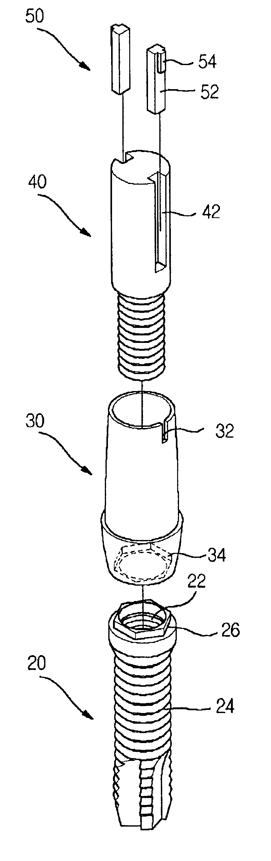
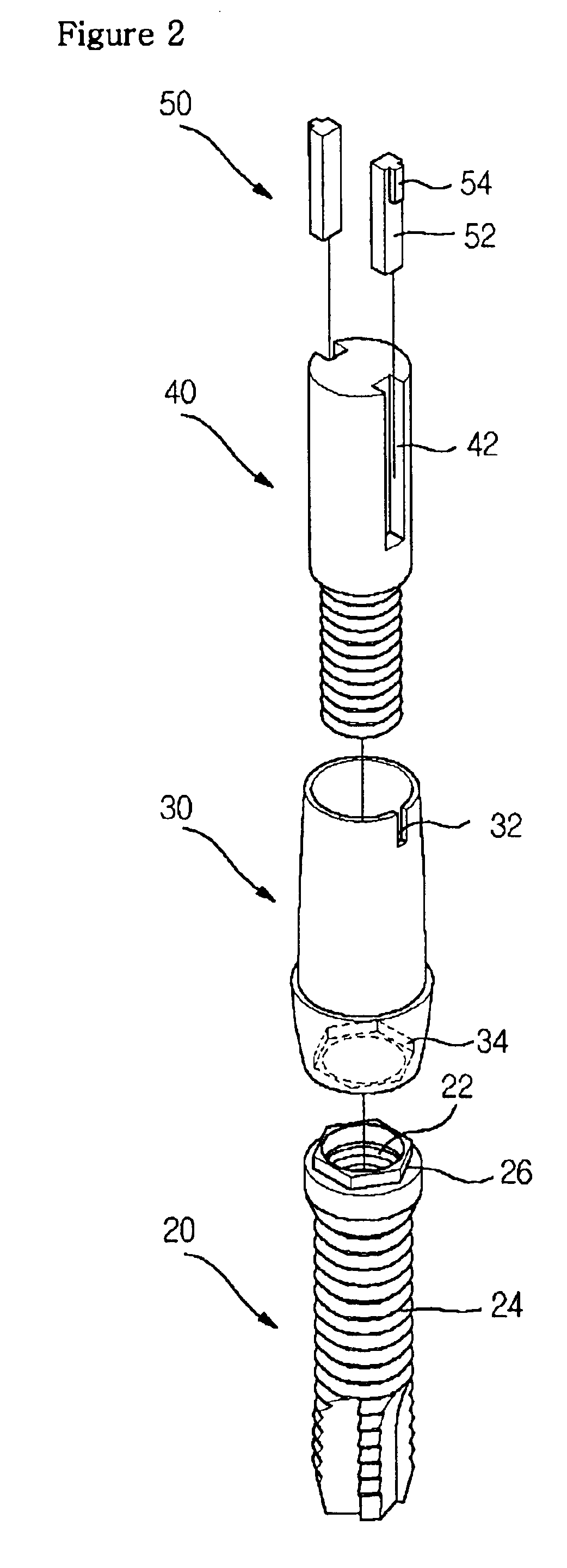
FIG. 2 is an exploded perspective view of a dental implant according to the present invention, FIG. 3 is a perspective view of the assembled dental implant of FIG. 2 according to the present invention, and FIG. 4 is a cross-sectional view taken along the line A—A of FIG. 3 according to the present invention.

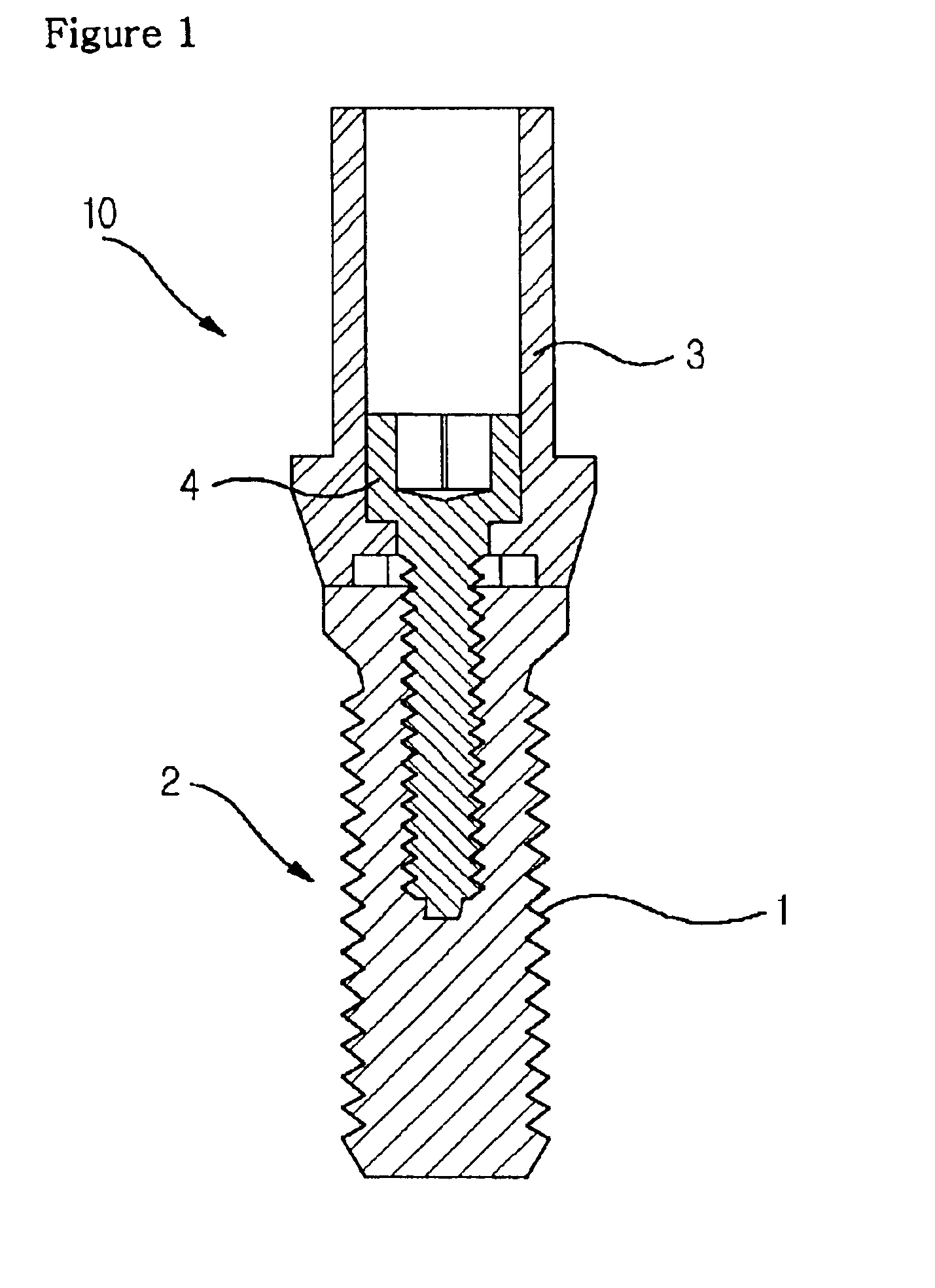
Referring to FIGS. 2 to 4, a dental implant includes: a fixture 20 having a screw coupling hole 22 formed at the inside thereof along the central axis thereof by a predetermined depth, the fixture being opened at the upper end thereof, and a threaded screw part 24 formed on the outer circumferential surface thereof; an abutment 30 secured to the upper end of the fixture 20 and having a locking slit 32 formed at the upper portion of the outer circumferential surface thereof; a screw 40 coupled to the screw coupling hole 22 of th...


PUM


Abstract

Disclosed is a dental implant which is implanted into an edentulous site of the jawbone to function as a substitute for a lost tooth. The dental implant according to the present invention includes: a fixture having a screw coupling hole formed at the inside thereof along the central axis thereof by a predetermined depth, the fixture being opened at the upper end thereof, and a threaded screw part formed on the outer circumferential surface thereof; an abutment secured to the upper end of the fixture and having a locking slit formed at the upper portion of the outer circumferential surface thereof; a screw coupled to the screw coupling hole of the fixture through the abutment and having a sleeve inserting groove formed at the upper portion thereof to be connected to the locking slit of the abutment; and a locking sleeve fitted into both the locking slit of the abutment and the sleeve inserting groove of the screw.

Description

BACKGROUND OF THE INVENTION1. Field of the InventionThe present invention relates to a dental implant, and more particularly, to a dental implant which is embedded into an edentulous site of the jawbone to function as a substitute for a lost tooth.2. Background of the Related ArtA study on methods for finding a substitute for a tooth that is lost due to various reasons has been continued in dentistry. Clinical testing for finding the methods has been actively conducted as well. Among the methods, the most widely used method is to use a crown or a bridge as an artificial substitute for the lost tooth with the help of adjacent teeth, or to use a partial denture or a complete denture as the artificial substitute for the lost tooth with the help of both the adjacent teeth and gums(jawbone).The above crown or bridge is disadvantageous in that the adjacent healthy teeth should be pulled out, and if there are lots of lost teeth, the crown or bridge has a limitation in functioning as the ar...

Claims


Application Information

Patent Timeline
Patent Type & Authority Patents(United States)
IPC IPC(8): A61C8/00
CPCA61C8/005A61C8/0068A61C8/0059A61C8/006A61C8/00
Inventor KIM, MAN YONG
Owner KIM MAN YONG
Why Eureka
Try Eureka