Transmission load modeling for engine idle speed control

a technology of transmission load and engine idle speed, which is applied in the direction of electric control, speed sensing governor, machines/engines, etc., can solve the problems of reducing the torque output of the engine, noticeable fluctuation of engine idle speed, and both methods, however, have disadvantages

Inactive Publication Date: 2005-02-22
GM GLOBAL TECH OPERATIONS LLC
View PDF3 Cites 15 Cited by
  • Summary
  • Abstract
  • Description
  • Claims
  • Application Information

AI Technical Summary

Problems solved by technology

Powering each of these auxiliary components reduces the torque output of the engine.
During idle, the reduced torque output may cause noticeable fluctuation of engine idle speed.
Both methods, however, have disadvantages.
Spark retard causes inefficient engine operation during idle.
Other auxiliary components such as the hydraulic pump do not provide feedback signals to the engine controller.
When the transmission load requires increased hydraulic pressure, the hydraulic pump increases the load on the engine, which fluctuates engine idle speed.

Method used


Image

  • Transmission load modeling for engine idle speed control
  • Transmission load modeling for engine idle speed control
  • Transmission load modeling for engine idle speed control

Examples


Embodiment Construction

The following description of the preferred embodiment is merely exemplary in nature and is in no way intended to limit the invention, its application, or uses. For purposes of clarity, the same reference numbers will be used in the drawings to identify similar elements.

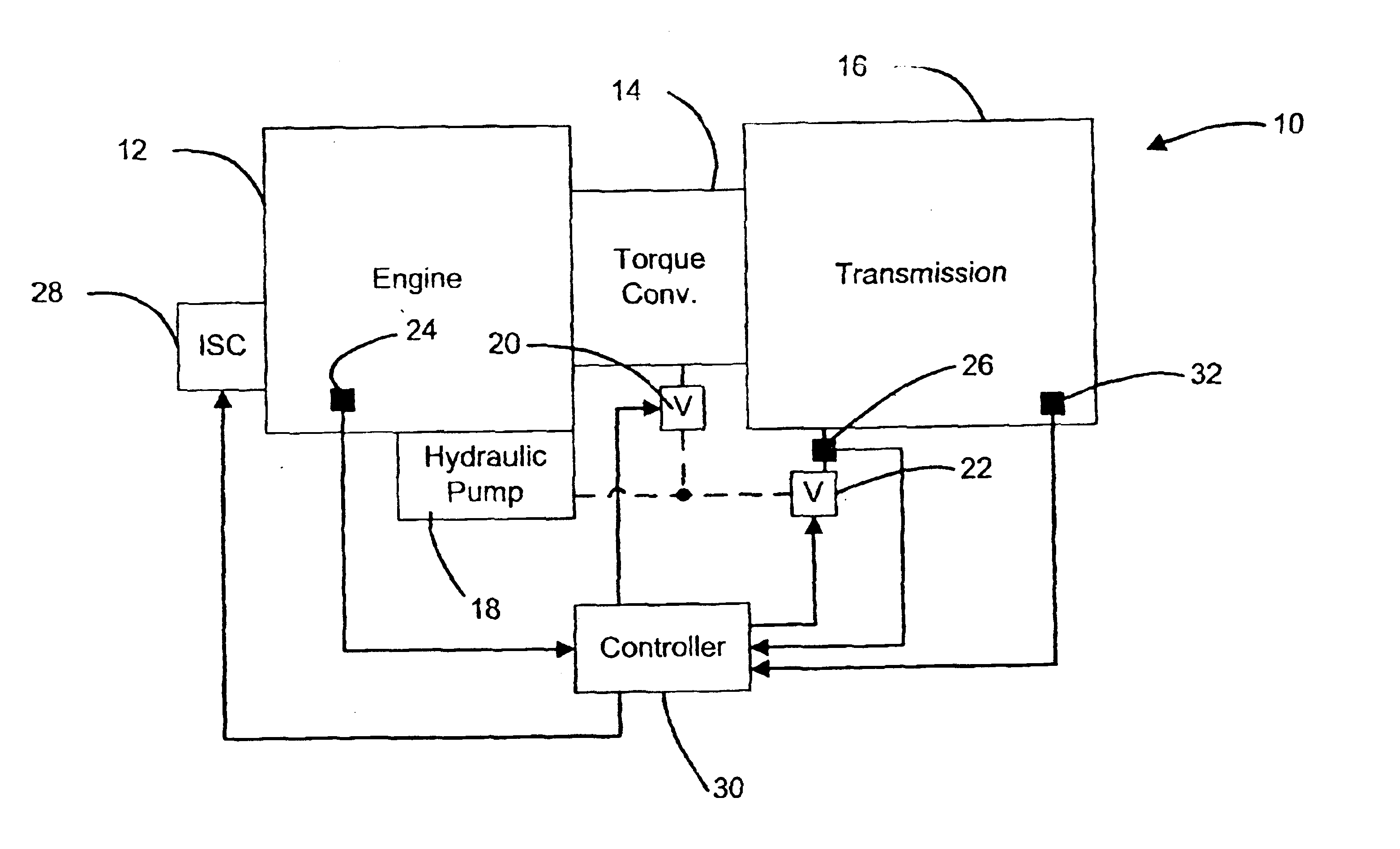
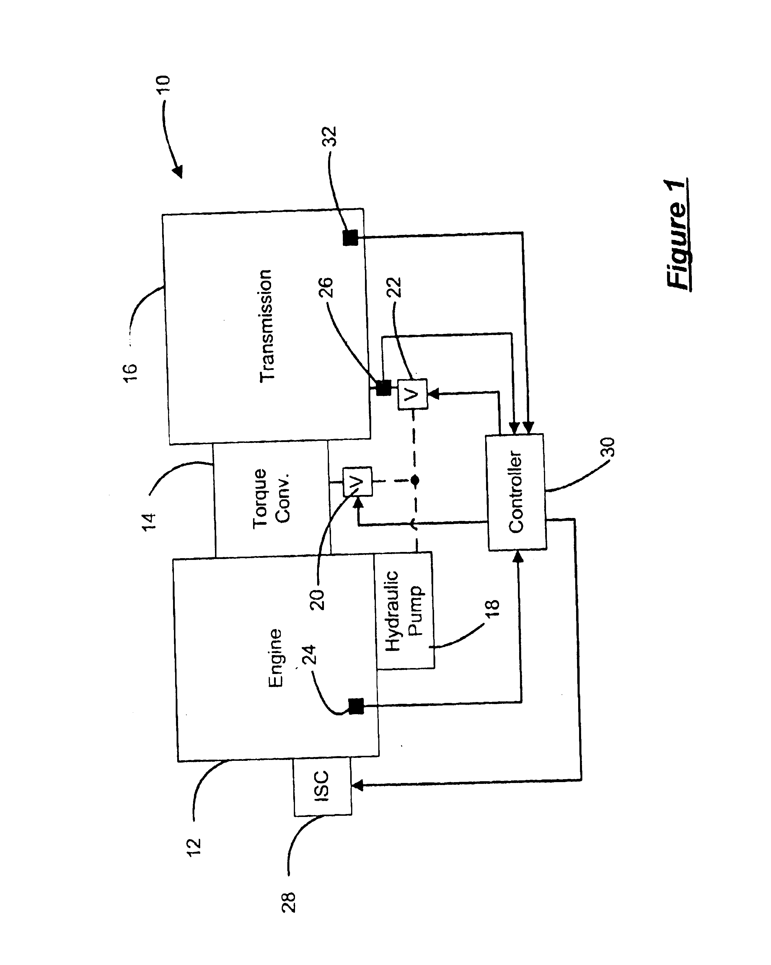
Referring now to FIG. 1, a vehicle 10 includes an engine 12, a torque converter 14, and an automatic transmission 16. The engine 12 drives the transmission 16 through the torque converter 14. A hydraulic pump 18 is driven by the engine 12 to provide pressurized fluid to the torque converter 14 and the transmission 16 through solenoid valves 20 and 22, respectively. Although not shown in the Figures it is anticipated that in an alternative configuration the hydraulic pump 18 can be part of the transmission 16. In this configuration, the hydraulic pump 18 is driven at engine speed by the torque converter 14.

An engine speed sensor 24 senses a rotational speed or revolutions per minute (RPMs) of the engine 12. A pressure ...


PUM


Abstract

An idle speed compensation system for a vehicle includes an idle speed control system that varies airflow to an engine at idle and a transmission driven by the engine. A controller communicates with the idle speed control system, the engine, and the transmission. The controller generates an idle speed compensation signal based on a transmission load.

Description

FIELD OF THE INVENTIONThe present invention relates to idle speed control, and more particularly to using a transmission load estimate to improve idle speed control.BACKGROUND OF THE INVENTIONBesides driving a powertrain, an engine of a vehicle provides power to various auxiliary components. These components typically include an alternator that recharges a battery, an A / C compressor for an A / C system, and / or a hydraulic pump that provides pressurized hydraulic fluid. Powering each of these auxiliary components reduces the torque output of the engine. During idle, the reduced torque output may cause noticeable fluctuation of engine idle speed.Traditionally, controllers use spark retard and idle air control to reduce engine idle speed fluctuations. Both methods, however, have disadvantages. Spark retard causes inefficient engine operation during idle. Idle air control enables only gross tuning of the engine idle speed.Some of the auxiliary components such as the alternator and A / C com...

Claims


Application Information

Patent Timeline
Patent Type & Authority Patents(United States)
IPC IPC(8): F02D41/08F02D41/02F02D31/00
CPCF02D41/0215F02D41/083F02D31/003Y10T477/675Y10T477/68Y10T477/679
Inventor ALDRICH, III, WILLIAM L.O'CONNELL, GLENN P.VELLIKY, MICHAEL L.WOZNIAK, LEONARD G.PARSONS JR., RICHARD E.
Owner GM GLOBAL TECH OPERATIONS LLC
Why Eureka
Try Eureka