
Motor engine electric control fuel oil spraying system

A fuel injection system and engine technology, applied in engine control, fuel injection control, machine/engine, etc., can solve the problems of poor work reliability, poor system work stability, narrow adaptability, etc., and achieve reliable work performance, reasonable design, The effect of perfect system structure

Inactive Publication Date: 2008-03-19
西安易道汽车电器有限责任公司 +2
View PDF0 Cites 25 Cited by
  • Summary
  • Abstract
  • Description
  • Claims
  • Application Information

AI Technical Summary

Problems solved by technology

[0002] The existing motorcycle electronically controlled fuel injection system solutions have the following problems: (1) In order to reduce costs, the system is too simple, resulting in low fuel control accuracy and poor system stability
(2) The system is too simple and the control function is not perfect
There are two kinds of idle speed control mechanism at present: one is the method of manually adjusting the idle speed screw, and the other is the method of adjusting the air intake at idle speed by using a proportional solenoid valve. The former has a single function and narrow scope of application, while the latter has poor reliability. Not compact
(3) In order to simplify the system, the crankshaft position signal generating device of some electronically controlled fuel injection systems still uses the ignition trigger device and corresponding sensor of the original carburetor engine CDI ignition system. Since the trigger device has only one or two teeth, Therefore, the accuracy and stability of the ignition advance angle output by the electronic control system according to the crankshaft position signal are poor, let alone the function of using this signal to realize the engine working stability and misfire detection

Method used


Image

  • Motor engine electric control fuel oil spraying system
  • Motor engine electric control fuel oil spraying system
  • Motor engine electric control fuel oil spraying system

Examples


Embodiment Construction

[0013] The present invention will be further described below in conjunction with the accompanying drawings.

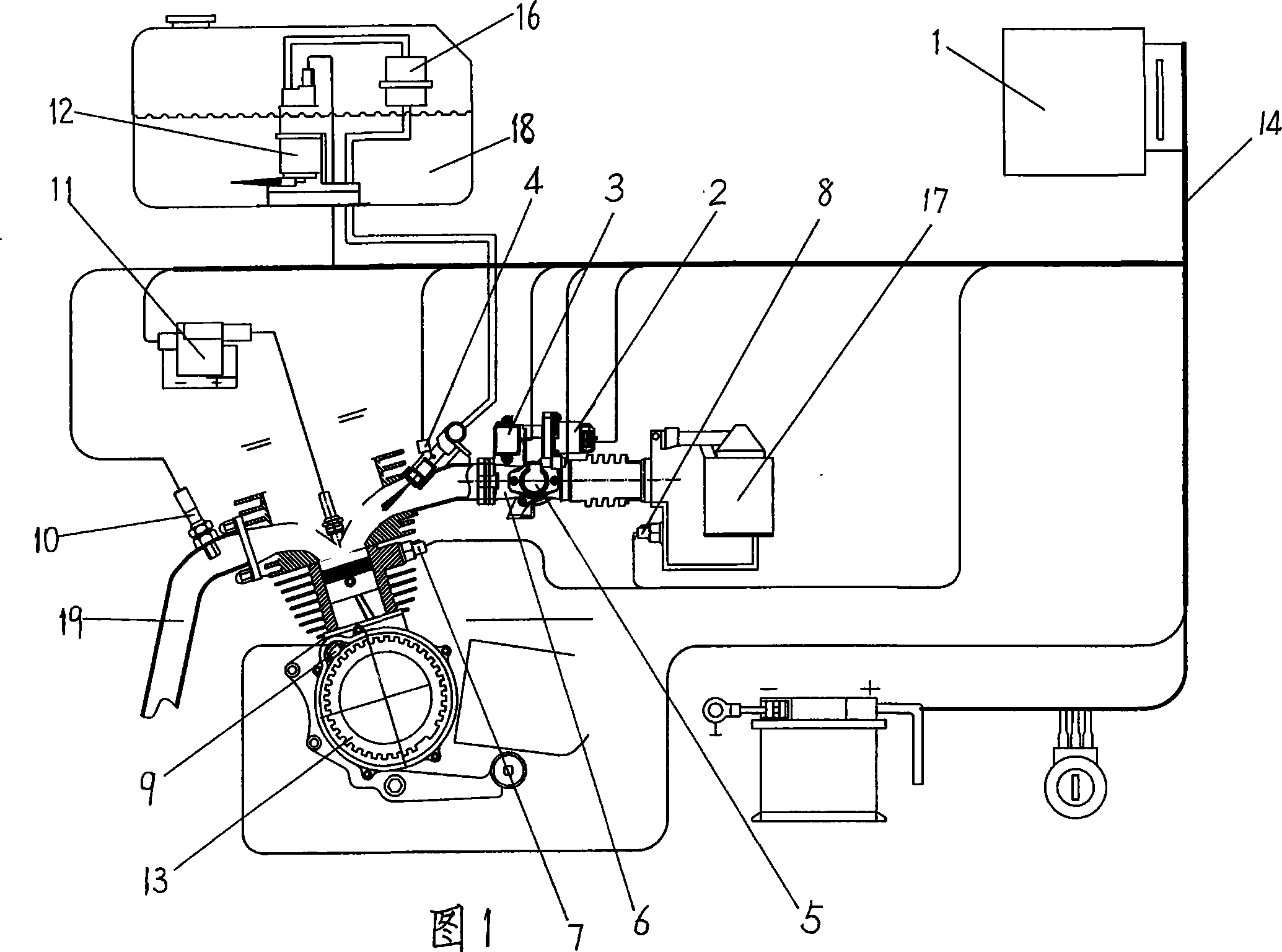
[0014] As shown in Fig. 1, the present invention comprises electronic control unit 1 and the sensor and actuator that are connected with electronic control unit 1 by wiring harness 14; The device 13 and the corresponding crankshaft position sensor 9, the throttle position sensor 5 installed on the throttle valve body 6, the intake air pressure sensor 3 connected with the intake pipe, and the intake air temperature sensor 8 installed on the air filter 17 And the cylinder temperature sensor 7 installed on the engine body and the oxygen sensor 10 installed on the exhaust pipe 19; the actuator includes the idle speed control valve 2 installed on the throttle body 6, the Electric fuel pump 12 and fuel pressure regulator 16, fuel injector 4 and ignition coil 11 installed at the cylinder head or throttle body.

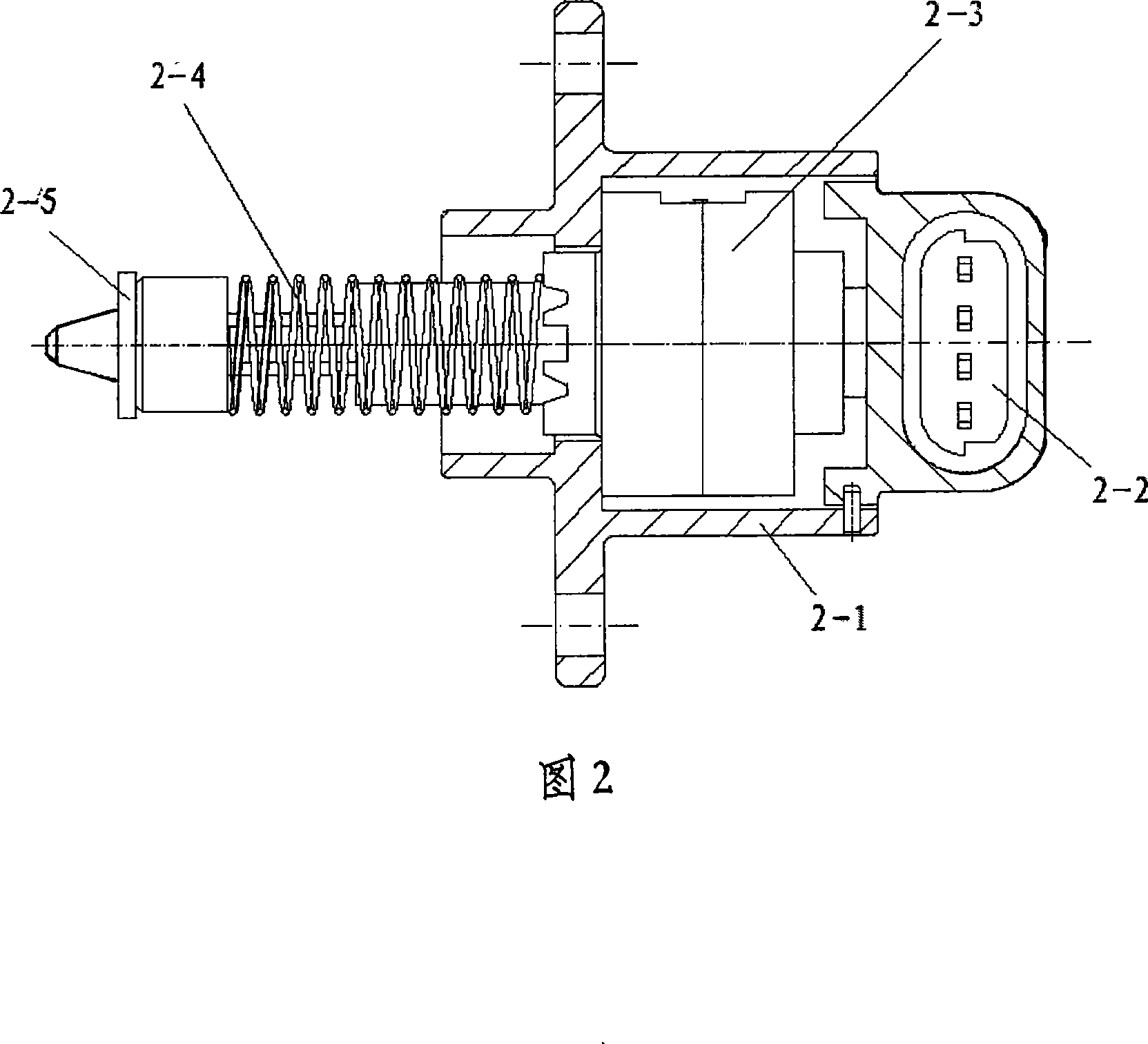
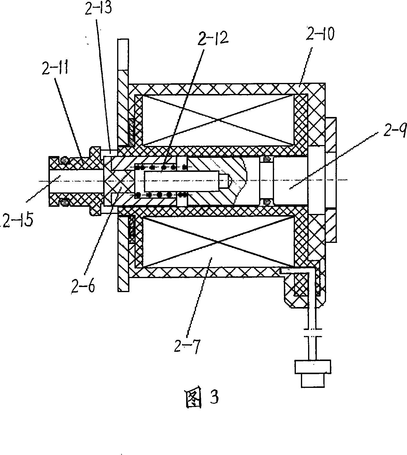
[0015] As shown in Figure 2, the idle speed control valve 2 is ...


PUM


Abstract

The invention discloses a motorcycle engine electronic control fuel injection system, and comprises an electronic control unit, and a sensor and an executive mechanism connected with the electronic control unit; the sensor comprises a crankshaft position signal generator, a crankshaft position sensor and a throttle position sensor corresponding to the crankshaft position signal generator, an intake pressure sensor communicated with an air intake tube, an intake air temperature sensor communicated with the air intake tube, a cylinder body temperature sensor installed on the engine body, and an oxygen sensor arranged on an exhaust tube, wherein, the executive mechanism comprises an idle speed control valve, an electric fuel pump, a fuel pressure regulator, an oil ejector and an ignition coil. The invention has the advantages that the design is reasonable, the structure of the system is perfect, the operating performance is stable and reliable, and the engine combines the electronic control system with the exhaust gas aftertreatment technology, to lead the exhaust gas emission to meet the requirements of the motorcycle country more than three issues emission regulation as well as the more than Euro III exhaust emission regulation.

Description

technical field [0001] The invention relates to a motorcycle engine fuel system, in particular to an electronically controlled fuel injection system for a motorcycle engine. Background technique [0002] The existing electronically controlled fuel injection system scheme for motorcycles has the following problems: (1) In order to reduce costs, the system is too simple, resulting in low fuel control accuracy and poor system stability. The current electronic control fuel injection system of motorcycle engine generally only adopts crankshaft position sensor, throttle position sensor, intake air temperature sensor, cylinder body temperature sensor and oxygen sensor, but no intake air pressure sensor and idle speed control valve etc. In this system, the throttle position and engine speed are used to calculate the basic fuel injection quantity and ignition advance angle, and on this basis, the basic fuel injection quantity and ignition advance angle are corrected by combining the ...

Claims


Application Information

Patent Timeline
IPC IPC(8): F02D43/00F02D41/08F02D41/30
Inventor 刘亦夫段保民李汉伟杨健伟陈含颖陈泉
Owner 西安易道汽车电器有限责任公司
Learn More