Idle speed control valve control system

a control system and valve technology, applied in electrical control, marine propulsion, vessel construction, etc., can solve the problems of engine stall or misfire, the air flow through the induction system does not properly match the desired change of engine speed, and the valves to move relatively slowly and incrementally

Inactive Publication Date: 2003-02-18
SANSHIN KOGYO CO LTD
View PDF5 Cites 24 Cited by
  • Summary
  • Abstract
  • Description
  • Claims
  • Application Information

AI Technical Summary

Problems solved by technology

This increased loading generally results from the nature of the outboard motor and the environment of use of the outboard motor.
In addition, these motors cause the valves to move relatively slowly and incrementally.
Because of the slow opening rate of the idle speed control valve, the air flow through the induction system

Method used


Image

  • Idle speed control valve control system
  • Idle speed control valve control system
  • Idle speed control valve control system

Examples


Embodiment Construction

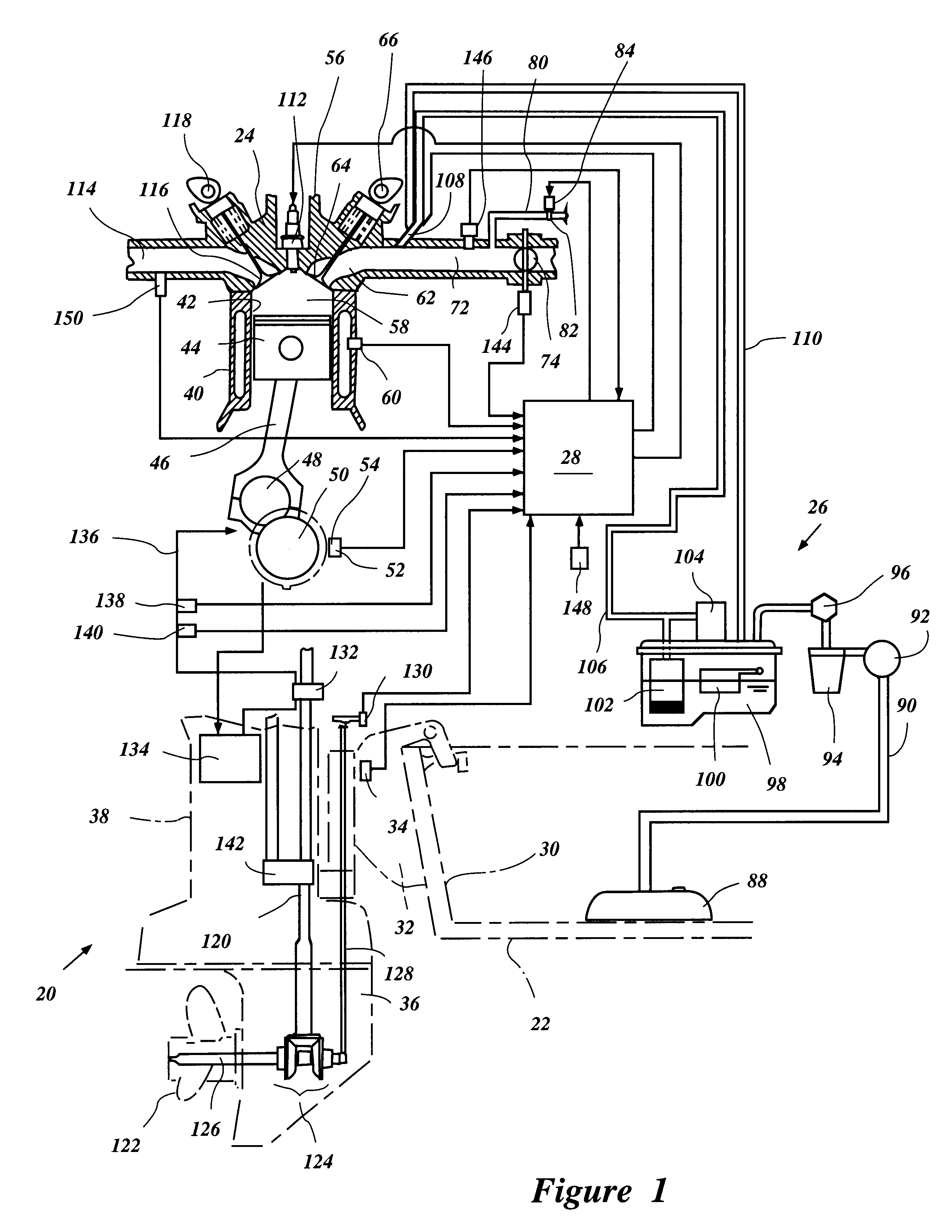
With reference now to FIG. 1, a portion of an outboard motor 20 attached to a watercraft 22 is illustrated. In addition, in FIG. 1, a portion of an engine 24 is shown in schematic cross-section. Furthermore, a portion of a fuel supply system 26, portions of the outboard motor 20, the engine 24 and the fuel system 26 are interconnected by an ECU or other suitable controller 28. While the present invention will be described in the context of an outboard motor that is attached to a watercraft, it should be apparent to those of ordinary skill in the art that the present invention can be used in other environments. For instance, the present invention may find utility in personal watercraft, small water vehicles, jet boats and the like. In particular, due to the unique operating characteristics of water vehicles, the present invention is particularly designed for use in such applications.

With continued reference to FIG. 1, the outboard motor 20 is attached to a transom 30 of the watercraf...


PUM


Abstract

An outboard motor comprises an engine mounted within an engine compartment. The engine comprises an induction system having an induction passage extending between an air intake box to a combustion chamber. A throttle valve is positioned along the passage. A bypass passage communicates with the passage at a location between the throttle valve and the combustion chamber. An adjustable valve controls flow through the bypass passage. The adjustable valve is opened as the throttle valve is opened or as the engine speed is increased. The adjustable valve is closed when the throttle valve is rapidly closed or when the engine speed is rapidly decreased.

Description

PRIORITY INFORMATIONThis application is based on and claims priority to Japanese Patent Application No. 11-293055, filed Oct. 14, 1999, the entire contents of which is hereby expressly incorporated by reference.1. Field of the InventionThe present invention generally relates to idle speed controls for internal combustion engines used in marine applications. More specifically, the present invention relates to such systems in which throttle bypass levels are adjusted based on throttle valve positioning or engine speed.2. Related ArtOutboard motors are powered by engines contained within an engine compartment of the outboard motor. The outboard motors are conventionally attached to watercraft to power the watercraft in a forward or reverse direction. As is known, the engine of the outboard motor is subject to increased loading when compared to that of an automobile, for instance. This increased loading generally results from the nature of the outboard motor and the environment of use o...

Claims


Application Information

Patent Timeline
IPC IPC(8): F02M3/07F02M3/00F02B61/00F02B61/04F02D41/04F02D41/12
CPCF02M3/07F02B61/045
Inventor KANNO, ISAO
Owner SANSHIN KOGYO CO LTD
Why Eureka
Try Eureka