External exhaust gas recirculation on board diagnostic using EGR effect on a combination of engine operating parameters

Active Publication Date: 2005-02-01
JAGUAR LAND ROVER LTD
View PDF15 Cites 24 Cited by
  • Summary
  • Abstract
  • Description
  • Claims
  • Application Information

AI Technical Summary

Benefits of technology

By utilizing both a change in manifold pressure and operation of the second valve, it is possible to accurately identify degradation of the EGR system. For example, in the case where a second valve is a throttle (or a bypass valve) maintaining engine idle

Problems solved by technology

However, degradation in EGR components can lead to degraded EGR operation.
The inventors herein however, have recognized a disadvantage with such an approach.
In particular, as emission requirements become greater and greater, simply using a single detection parameter can lead to inaccurate detection.
The inve

Method used


Image

  • External exhaust gas recirculation on board diagnostic using EGR effect on a combination of engine operating parameters
  • External exhaust gas recirculation on board diagnostic using EGR effect on a combination of engine operating parameters
  • External exhaust gas recirculation on board diagnostic using EGR effect on a combination of engine operating parameters

Examples


Embodiment Construction

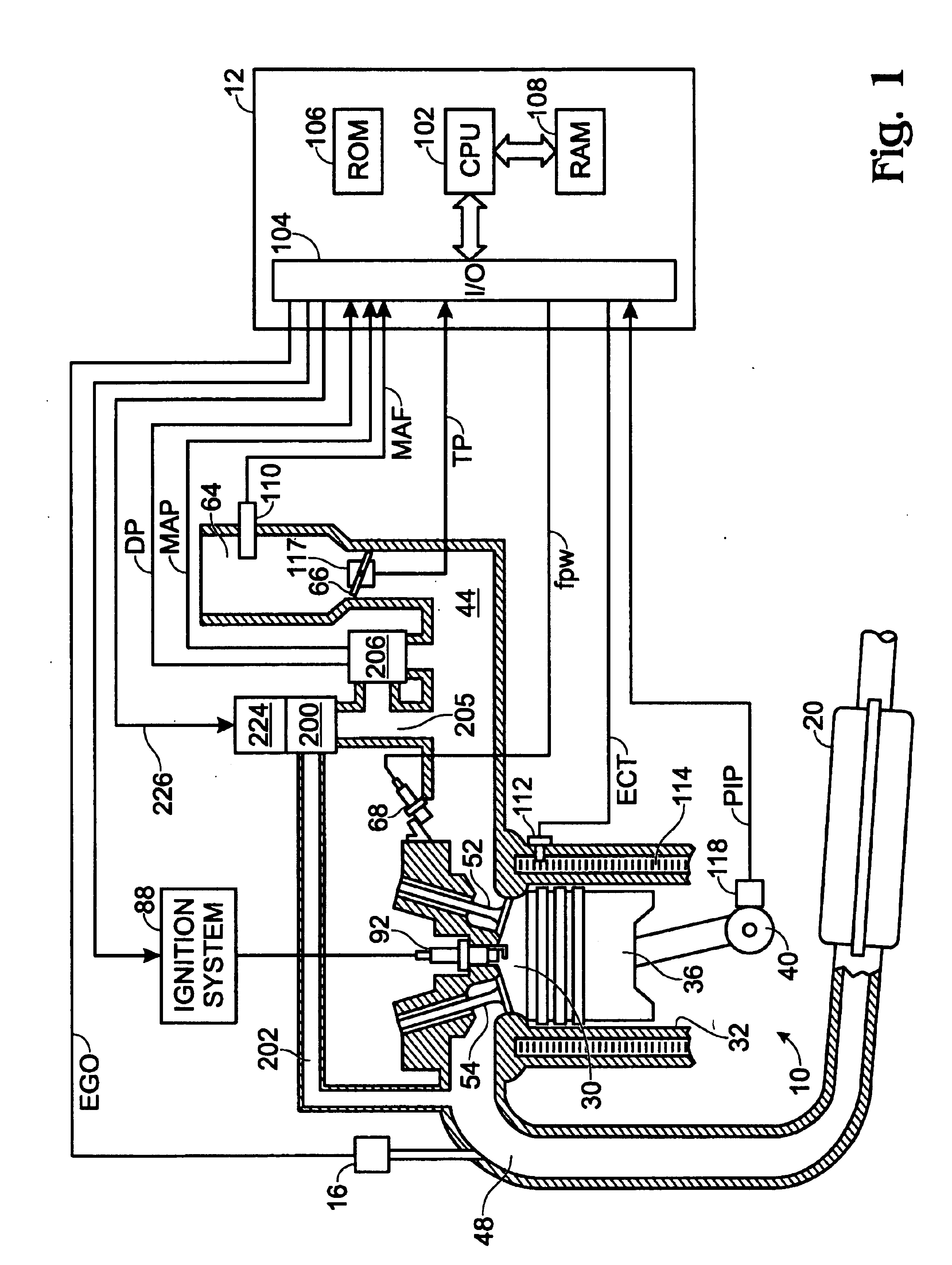
Internal combustion engine 10 comprising a plurality of cylinders, one cylinder of which is shown in FIG. 1, is controlled by electronic engine controller 12. Engine 10 includes combustion chamber 30 and cylinder walls 32 with piston 36 positioned therein and connected to crankshaft 40. Combustion chamber 30 communicates with intake manifold 44 and exhaust manifold 48 via respective intake valve 52 and exhaust valve 54. Exhaust gas oxygen sensor 16 is coupled to exhaust manifold 48 of engine 10 upstream of catalytic converter 20.

Intake manifold 44 communicates with throttle body 64 via throttle plate 66. Intake manifold 44 is also shown having fuel injector 68 coupled thereto for delivering fuel in proportion to the pulse width of signal (fpw) from controller 12. Fuel is delivered to fuel injector 68 by a conventional fuel system (not shown) including a fuel tank, fuel pump, and fuel rail (not shown). Engine 10 further includes conventional distributorless ignition system 88 to prov...


PUM


Abstract

A system is described for determining degradation of an exhaust gas recirculation system of an internal combustion engine. This method utilizes a combination of parameters to accurately determine degradation of the exhaust gas recirculation system. For example, the system utilizes changes in intake manifold pressure, changes in idle speed control operation, changes in ignition timing, and fueling changes to accurately determine operation of the exhaust gas recirculation system.

Description

FIELD OF THE INVENTIONThe field of the present invention relates generally to routines and methods for determining degradation in an exhaust gas recirculation system.BACKGROUND OF THE INVENTIONEngine systems utilize exhaust gas recirculation (EGR) to reduce engine generated NOx emissions, while at the same time increasing fuel economy by reducing engine pumping work. In EGR systems, exhaust gas from the exhaust manifold is typically routed to the intake manifold downstream of the engine throttle plate. However, degradation in EGR components can lead to degraded EGR operation. As such, various methods are available to monitor and diagnose such EGR degradation.One such method is described in U.S. Pat. No. 4,715,348 (Kobayashi et al.). In this system, several embodiments are described for determining degradation of an EGR system. In one embodiment, variation in intake manifold pressure is used. In another embodiment, variation in the detected intake air amount is utilized. In still ano...

Claims


Application Information

Patent Timeline
IPC IPC(8): F02D31/00F02D21/00F02D41/22F02D21/08F02M25/07F02D41/00
CPCF02D31/003F02D41/0055F02M25/0702F02M25/0755F02D41/0047Y02T10/47F02D2200/0406F02M26/46F02M26/49Y02T10/40F02D41/221
Inventor SUMMERS, DAVID HOWARDSUTTON, SIMON OLIVERKING, PAUL JOHN
Owner JAGUAR LAND ROVER LTD
Why Eureka
Try Eureka