Blood withdrawal system

Inactive Publication Date: 2005-02-22
ROCHE DIABETES CARE INC
View PDF11 Cites 138 Cited by
  • Summary
  • Abstract
  • Description
  • Claims
  • Application Information

AI Technical Summary

Benefits of technology

In spite of the extensive development work resulting in the designs mentioned and several further designs, there is substantial interest in a blood withdrawal system which complies wi

Problems solved by technology

The freedom of movement of the lancet during the cocking movement is limited i

Method used


Image

  • Blood withdrawal system
  • Blood withdrawal system
  • Blood withdrawal system

Examples


Example

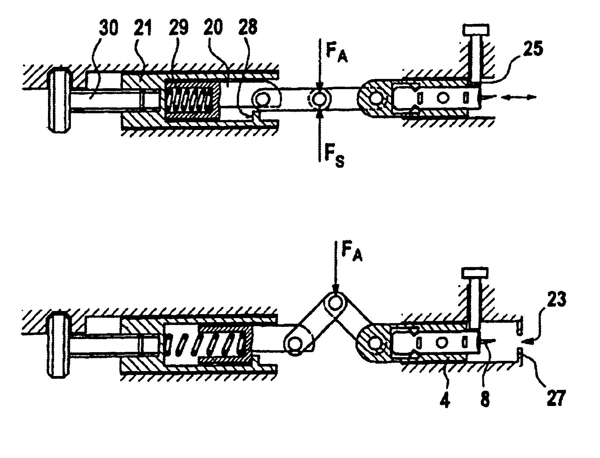
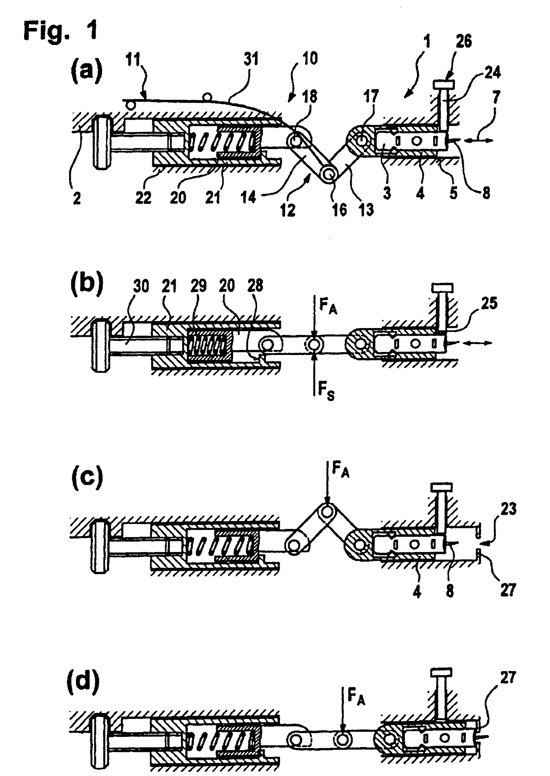
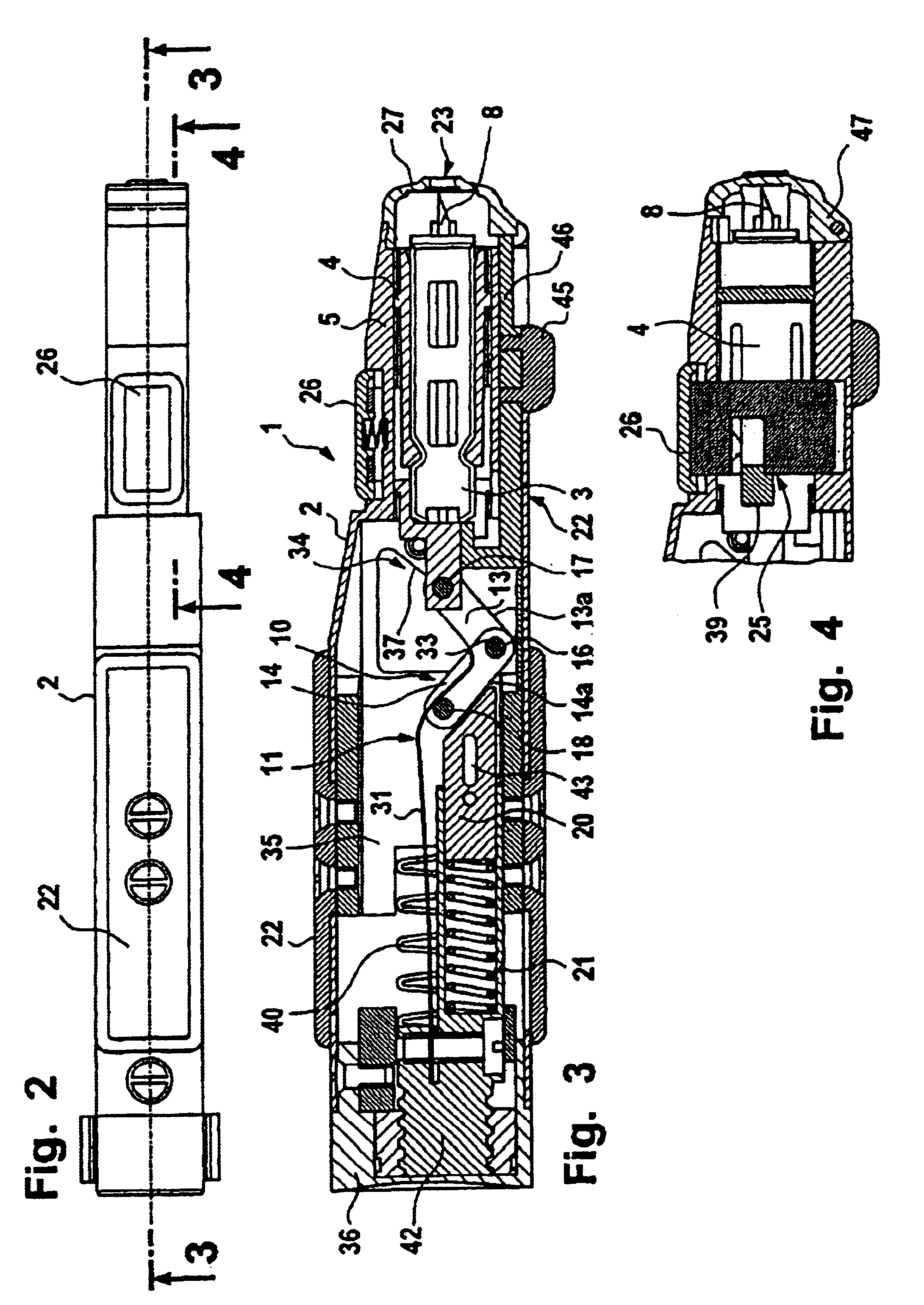
The blood withdrawal system 1 comprises a puncturing device 2 (only partially shown in FIGS. 1 and 5) and lancets 3. In the shown embodiments, the lancet 3 is exchangably fixed in a lancet holder 4. The lancet holder 4 is guided by a lancet guide 5 during the puncturing movement of the lancet on a predetermined puncture path 7. Thus, the guiding of the lancet 3 on the puncture path 7 is achieved indirectly via the lancet holder 4. The invention is, however, also usable with “directly guided” lancets which are during the puncturing movement coupled to the lancet drive of the puncturing device only with the end opposed to the lancet tip 8, and guided directly (in particular by the surrounding housing wall).

During the puncturing and retraction movement, the lancet 3 is coupled (in the shown embodiment indirectly via the lancet holder 4) to a lancet drive 10, which essentially consists of a drive element 11 and a power transmission coupling mechanism, in the case of the invention a plur...


PUM


Abstract

Blood withdrawal system for withdrawing blood for diagnostic purposes, comprising a housing with an outlet opening for the tip of a lancet, a lancet guide and a lancet drive. The lancet drive comprises a plural lever coupling mechanism, forming a connection between the drive element and the lancet during the puncturing movement and comprising two levers connected to each other via a first swivel joint, wherein one of the levers is coupled to the lancet with its end facing towards the lancet by means of a second swivel joint, and the second lever comprises a third swivel joint at the end facing away from the lancet. During the cocking movement, the freedom of movement of the lancet is limited in such a manner that the lancet tip does not protrude from the outlet opening.

Description

RELATED APPLICATIONThis application claims the benefit of German patent application no. 101 21 883.4, filed May 5, 2001.BACKGROUNDIn order to withdraw a small amount of blood from a body part (usually the finger or the earlobe) for analytic-diagnostic purposes, lancets are used which are punctured into the corresponding body part. If the lancets are punctured manually into the skin in order to generate a wound, specially trained staff is necessary. In any case, the puncturing procedure generates considerable pain.For a long time already, blood withdrawal systems are used which consist of a puncturing device and associated lancets, adapted to the corresponding device. A housing of the puncturing device contains a lancet drive for mechanically driving the lancet into the skin. Normally a spring is used as drive element for the puncturing movement. In an early development phase very simple designs were used, wherein the lancet was fixed directly to the end of a pressure spring located ...

Claims


Application Information

Patent Timeline
IPC IPC(8): A61B5/15A61B5/151
CPCA61B5/1411A61B5/15142A61B5/14514A61B5/150022A61B5/150412A61B5/15111A61B5/15117A61B5/1519A61B5/15194A61B5/150198A61B5/15113A61B5/150503
Inventor LIST, HANS
Owner ROCHE DIABETES CARE INC
Why Eureka
Try Eureka