Autostereoscopic display

a display and autostereoscopic technology, applied in the field of autostereoscopic display, can solve the problems of limiting the extent to which existing or conventional displays can be adapted to provide stereoscopic images, noise or moiré patterns of interference patterns,

Inactive Publication Date: 2005-02-22
MEMS OPTICAL
View PDF27 Cites 109 Cited by
  • Summary
  • Abstract
  • Description
  • Claims
  • Application Information

AI Technical Summary

Problems solved by technology

Furthermore, because the lenses were aligned, interference pattern noise or moiré patterns result from spatial mismatches between pixel edges and cylindrical lens edges when viewed off-axis.
However there are some limitations associated with that system and method when employed in connection with color pixel displays.
It also limits the extent to which existing or conventional displays can be adapted to provide stereoscopic images.
That is, it is not a simple matter to adapt a standard display to provide stereoscopic images because the display must be rotated ninety degrees to an orientation in which it is not intended to be used.

Method used


Image

  • Autostereoscopic display
  • Autostereoscopic display
  • Autostereoscopic display

Examples


Embodiment Construction

Reference will now be made in detail to the preferred embodiments of the present invention, examples of which are illustrated in the accompanying drawings. In the drawings, redundant description of like elements and processes, which are designated with like reference numerals, is omitted for brevity.

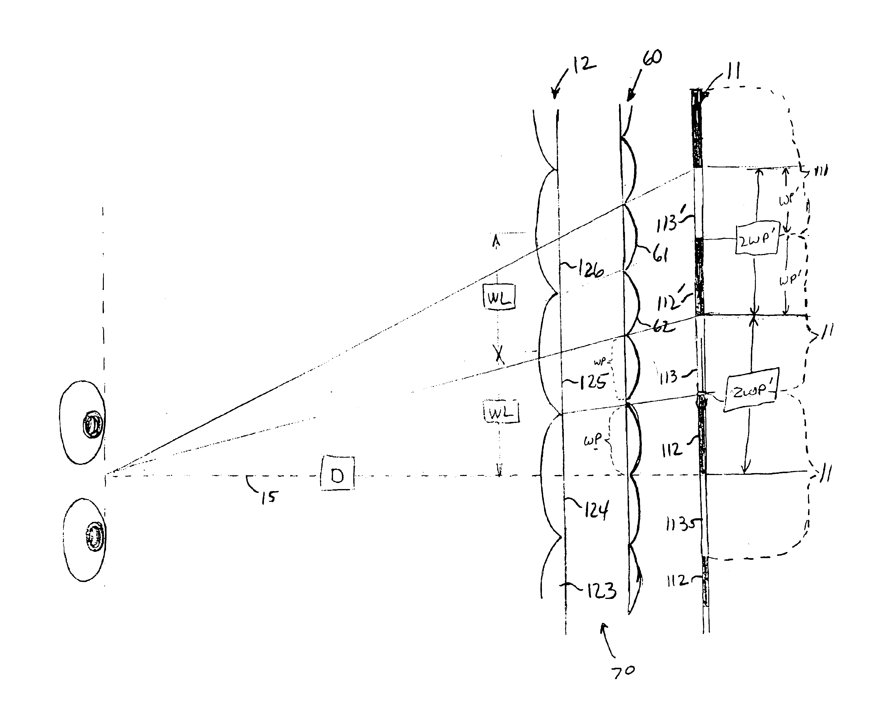
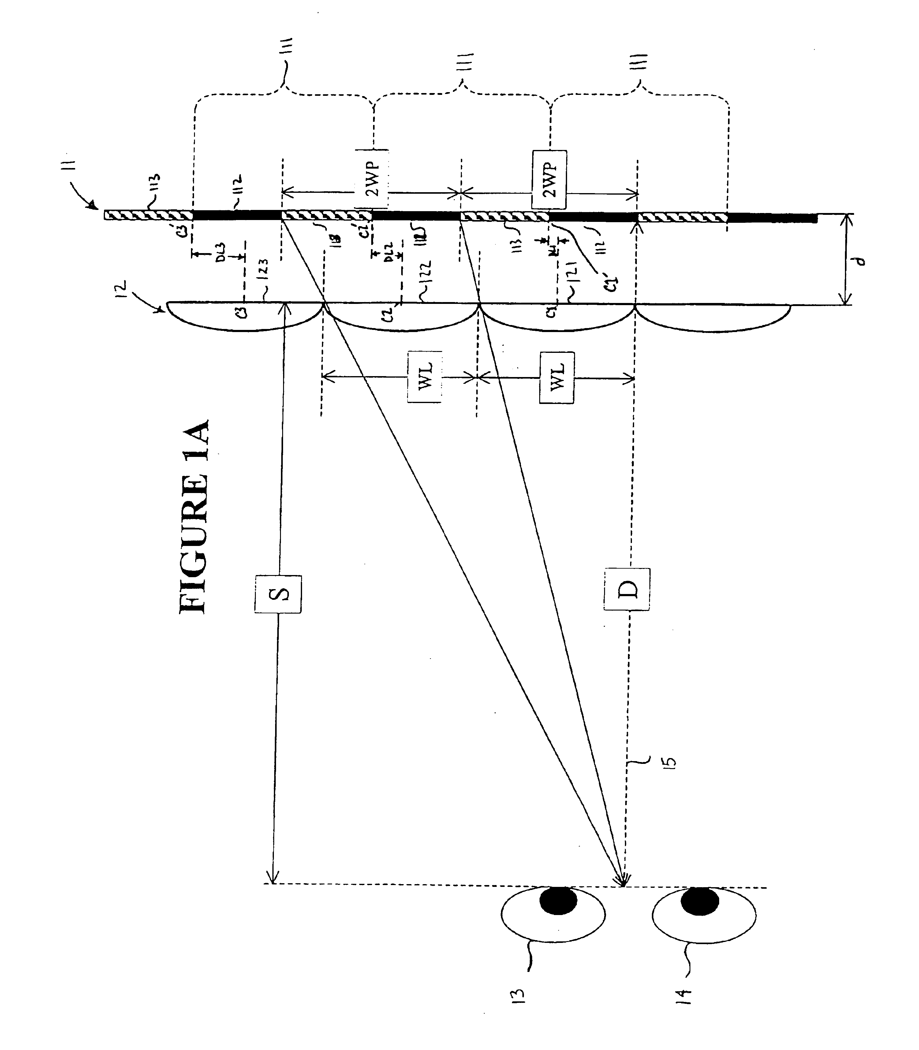
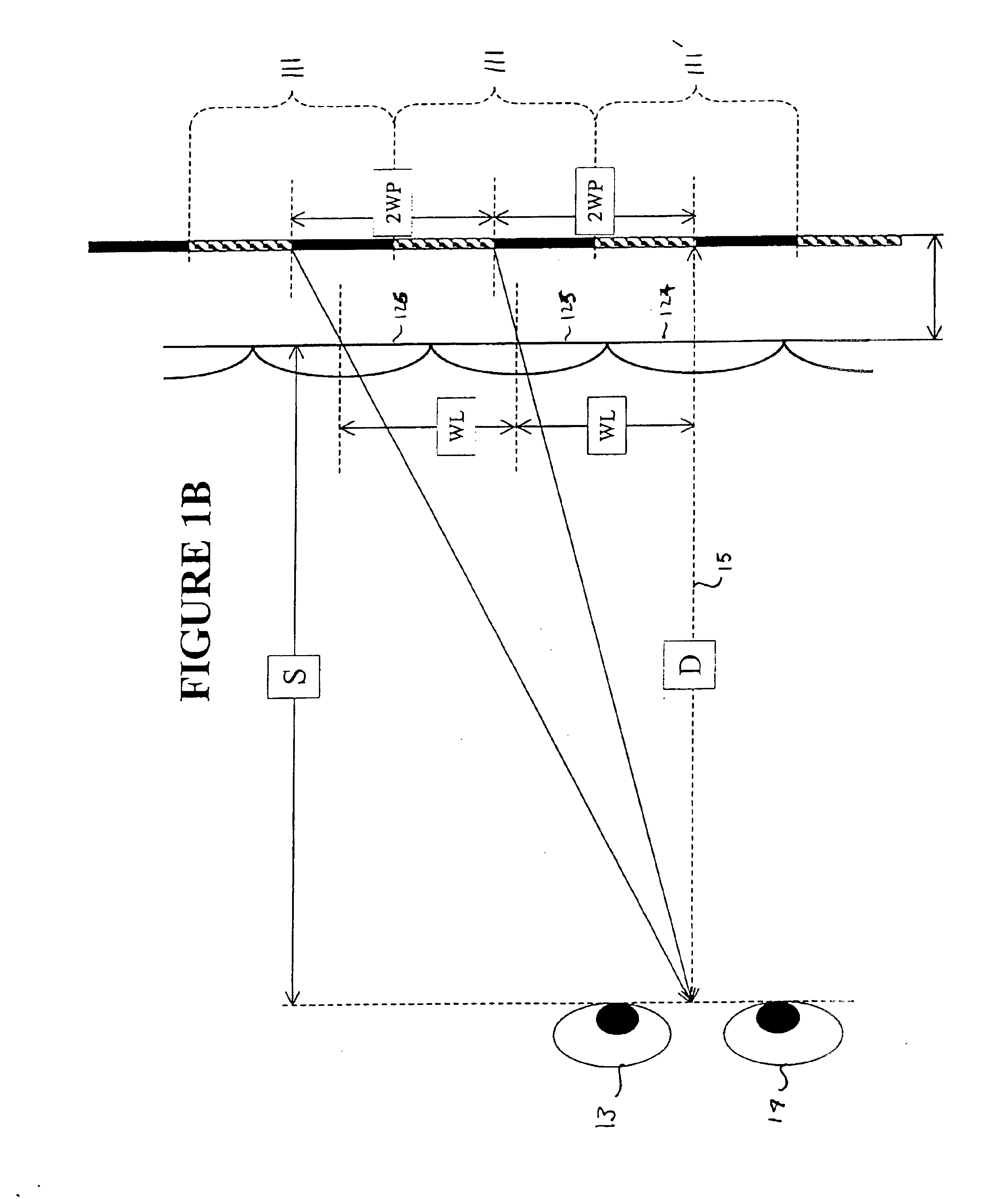
For a complete understanding of the present invention, reference is first made to the previously developed autostereoscopic display for an understanding of some of the underlying principles of structure and operation. FIG. 1A illustrates a top view of one embodiment of that autostereoscopic display.

The autostereoscopic display shown in FIG. 1A includes a pixel array 11 having several pixel groups 111 and a lenticular array 12 that is positioned adjacent pixel array 11. Pixel array 11 and lenticular array 12 are separated by a distance d that varies based on the desired or anticipated distance S between the viewer 13-14 and the front of the autostereoscopic display, as will be described l...


PUM

PropertyMeasurementUnit
distanceaaaaaaaaaa
fixed anglesaaaaaaaaaa
coloraaaaaaaaaa

Abstract

An autostereoscopic display and method of displaying multidimensional images involves a first lenticular array preferably of cylindrical lenses positioned between a viewer and a pixel array, and a second lenticular array also preferably of cylindrical lenses positioned between the first lenticular array and the viewer. The pixel array includes several pixel groups that project images through corresponding groups of first lenses within the first lenticular array. A pitch of the lenses within the second lenticular array differs from a pitch of the lenses in the first lens groups within the first lenticular array. The display can be manufactured or retrofit with the first and second lenticular arrays. By use of the first lenticular array, light from plural color pixels may be focussed to a single point so that color subpixels arranged in a direction transverse to the direction of the cylindrical lenses of the first lenticular array may be focussed to a single point on the secondary lenticular array and then as a single image to the user.

Description

BACKGROUND OF THE INVENTION1. Field of the InventionThe present invention is directed to an autostereoscopic display and method of displaying multidimensional images thereon. More particularly, the autostereoscopic display of the present invention includes two lenticular arrays positioned between a viewer and a pixel array. Lenses within the first lenticular array closest to the pixel array have a pitch that corresponds to the pitch of the color pixels of pixel array. Lenses within the second lenticular array have a different pitch than corresponding pixel groups within the pixel array. An autostereoscopic display in accordance with the present invention is particularly advantageous for creating stereoscopic displays in conjunction with color pixel arrays.2. Description of the Related ArtConventionally, three-dimensional displays of images have been achieved by using stereoscopic displays. A stereoscopic display is a display that provides multidimensional image cues to a viewer by c...

Claims


Application Information

Patent Timeline
Patent Type & Authority Patents(United States)
IPC IPC(8): G02B27/22H04N13/00G02B30/27
CPCG02B27/2214H04N13/0048H04N13/0447H04N13/0242H04N13/0404H04N13/0239H04N13/305H04N13/243H04N13/161H04N13/239H04N13/351G02B30/27
Inventor BROWN, DANIEL M.ERBACH, PETER
Owner MEMS OPTICAL
Why Eureka
Try Eureka