Optical fiber, and optical amplifier and transmission system including the optical fiber

a technology of optical fiber and transmission system, applied in the field of optical fibers, can solve the problems of deterioration of transmission characteristics, unsuitability for raman amplification in transmission system, and unsuitability of raman amplification optical fiber for raman amplification, which is applied to a transmission system without dispersion compensation,

Inactive Publication Date: 2005-02-22
FURUKAWA ELECTRIC CO LTD
View PDF12 Cites 22 Cited by
  • Summary
  • Abstract
  • Description
  • Claims
  • Application Information

AI Technical Summary

Benefits of technology

The present invention relates to an optical fiber with specific properties. The fiber has a small effective area, low dispersion, and a specific dispersion profile. It also has a high cut-off wavelength and low bending loss. The fiber has a core with at least two layers, and the refractive index difference between the layers is small. These properties make the optical fiber suitable for use in high-speed optical communication systems.

Problems solved by technology

The patent text discusses the use of optical fibers for Raman amplification in optical transmission systems. The technical problem being addressed is the development of optical fibers that are suitable for efficient and effective amplification using the Raman amplification technique. The text also mentions the use of rare earth elements, such as erbium, for amplification in WDM transmission systems and the use of Discreet Raman Amplification for improving transmission characteristics. The text concludes by stating that the DCF, which has a small effective area and a high non-linearity, is ideal for use as a Raman amplification component.

Method used


Image

  • Optical fiber, and optical amplifier and transmission system including the optical fiber
  • Optical fiber, and optical amplifier and transmission system including the optical fiber
  • Optical fiber, and optical amplifier and transmission system including the optical fiber

Examples


embodiment

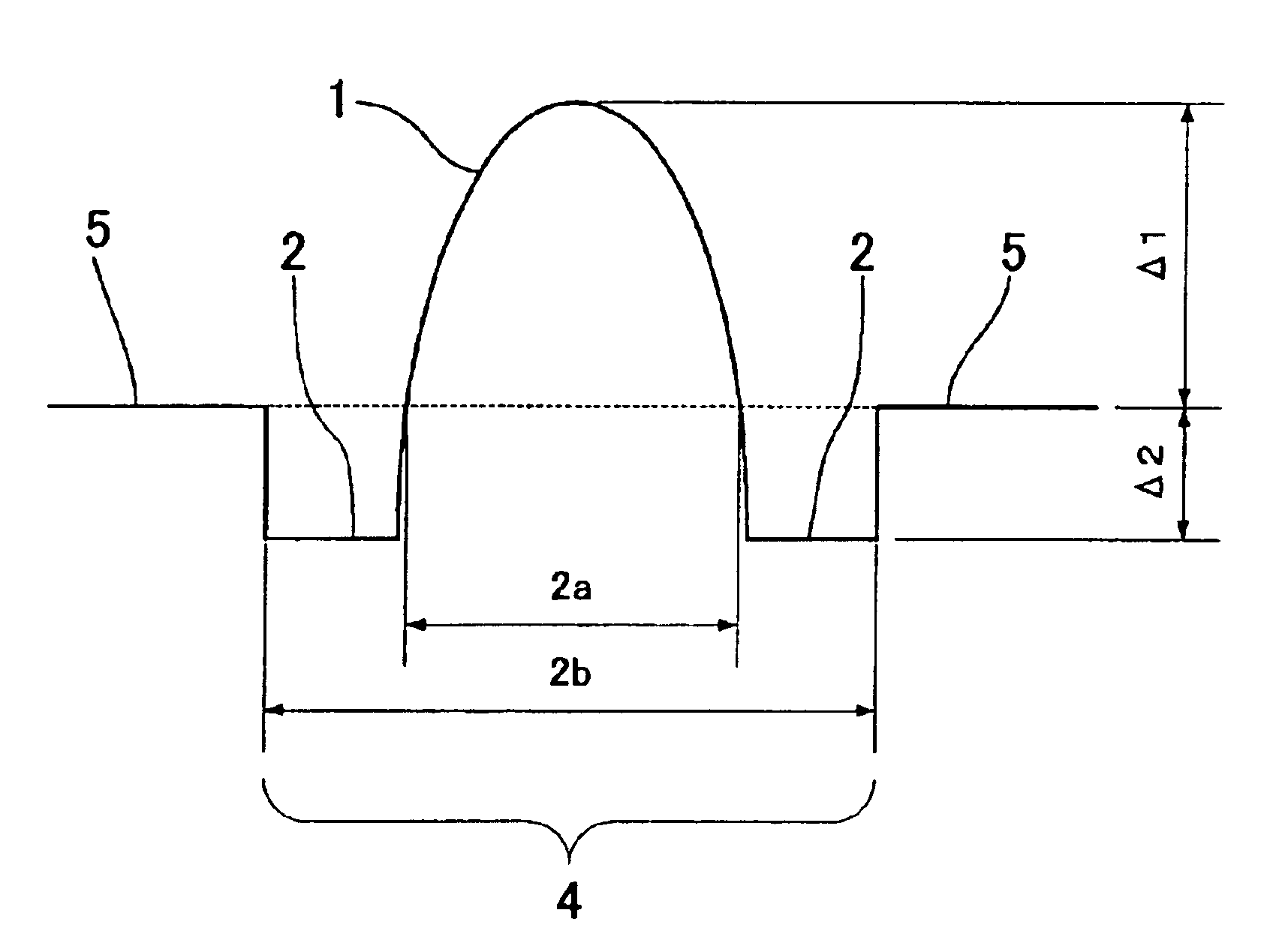
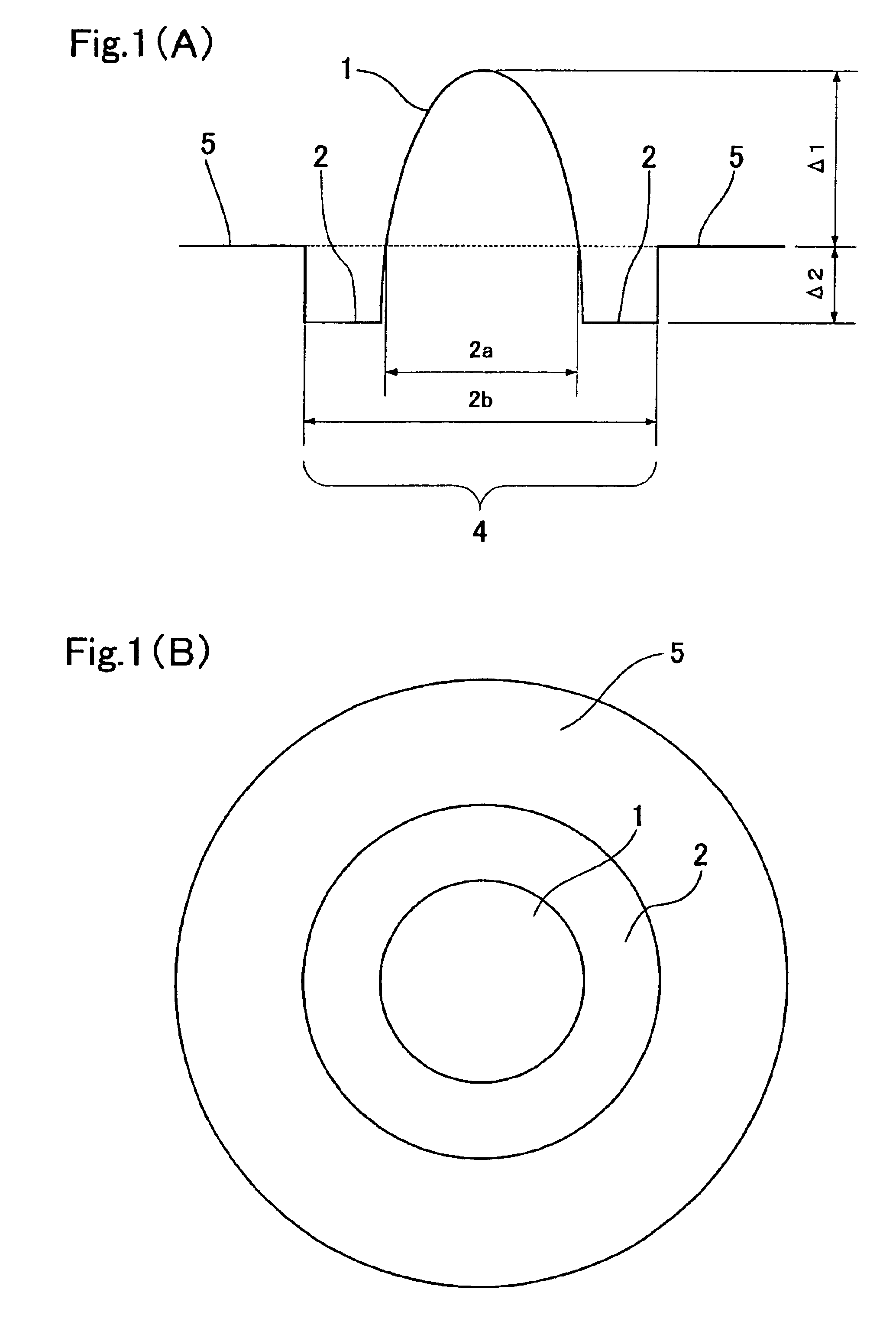
Now explained are substantial optical fibers in the first embodiment and the second embodiment, i.e., tangible data in bold numbers in the forth row from the top in Table 1 is substantiated to be a trial optical fiber, targeting in relative refractive index difference Δ1=2.4%, α=2, relative refractive index difference Δ2=−0.9%, a / b=0.30, core diameter=12.0 μm. This trial optical fiber 1 is described in No. 1, Table 3.

Note: The cutoff wavelength was found in a test method described in ITU-T G. 650.1.

TABLE 3DispersionTransmissionBendingDispersionSlopeλ0LossAeffn2 / AeffλcLossPMDNo.ps / nm / kmps / nm2 / kmnmdB / kmμm210−10 / WnmdB / mps / √km1−13.70.01421320.579.845.010260.10.112−16.00.00227350.589.149.110530.20.14

Additionally, tangible data in bold numbers in the second row from the top in Table 2 is substantiated to be a trial optical fiber, targeting in relative refractive index difference Δ1=2.4%, α=10, relative refractive index difference Δ2=−0.9%, a / b=0.3, c / b=1.45, core diameter(2b)=10.6 μm. Thi...


PUM


Abstract

Optical fibers with high non-linearity and low dispersion suitable for the Raman amplification are offered. Their structural and characteristic specifics are as follows: first core 1 with α profile surrounded with second core 2, further second core surrounded with cladding 5; setting first core 1 for no less than 1.8% of relative refractive index difference from cladding 5; setting second core 2 for no more than −0.4% of relative refractive index difference from cladding 5, setting α for 1.5 or larger, making second core 2 at least 2.2 times as large as first core 1 in diameter; and an effective area of no more than 15 μm2, a dispersion slope of 0.05 ps/nm2/km or lower in absolute value, a dispersion of no less than 5 ps/nm/km and no more than 20 ps/nm/km, in absolute value, a cutoff wavelength of 1350 nm or shorter, and a bending loss of 5.0 dB or lower in a bending diameter of 20 mm, each at a wavelength of 1.55 μm.

Description


Claims


Application Information

Patent Timeline
Owner FURUKAWA ELECTRIC CO LTD
Why Eureka
Try Eureka