Multimode Fiber With At Least Dual Cladding

a multi-mode fiber and cladding technology, applied in the field of optical fibers, can solve the problems of limiting the bandwidth of multi-mode fibers, reducing the losses due to micro-bending and cladding absorption, and high loss

Inactive Publication Date: 2010-02-18
CORNING INC
View PDF13 Cites 40 Cited by
  • Summary
  • Abstract
  • Description
  • Claims
  • Application Information

AI Technical Summary

Benefits of technology

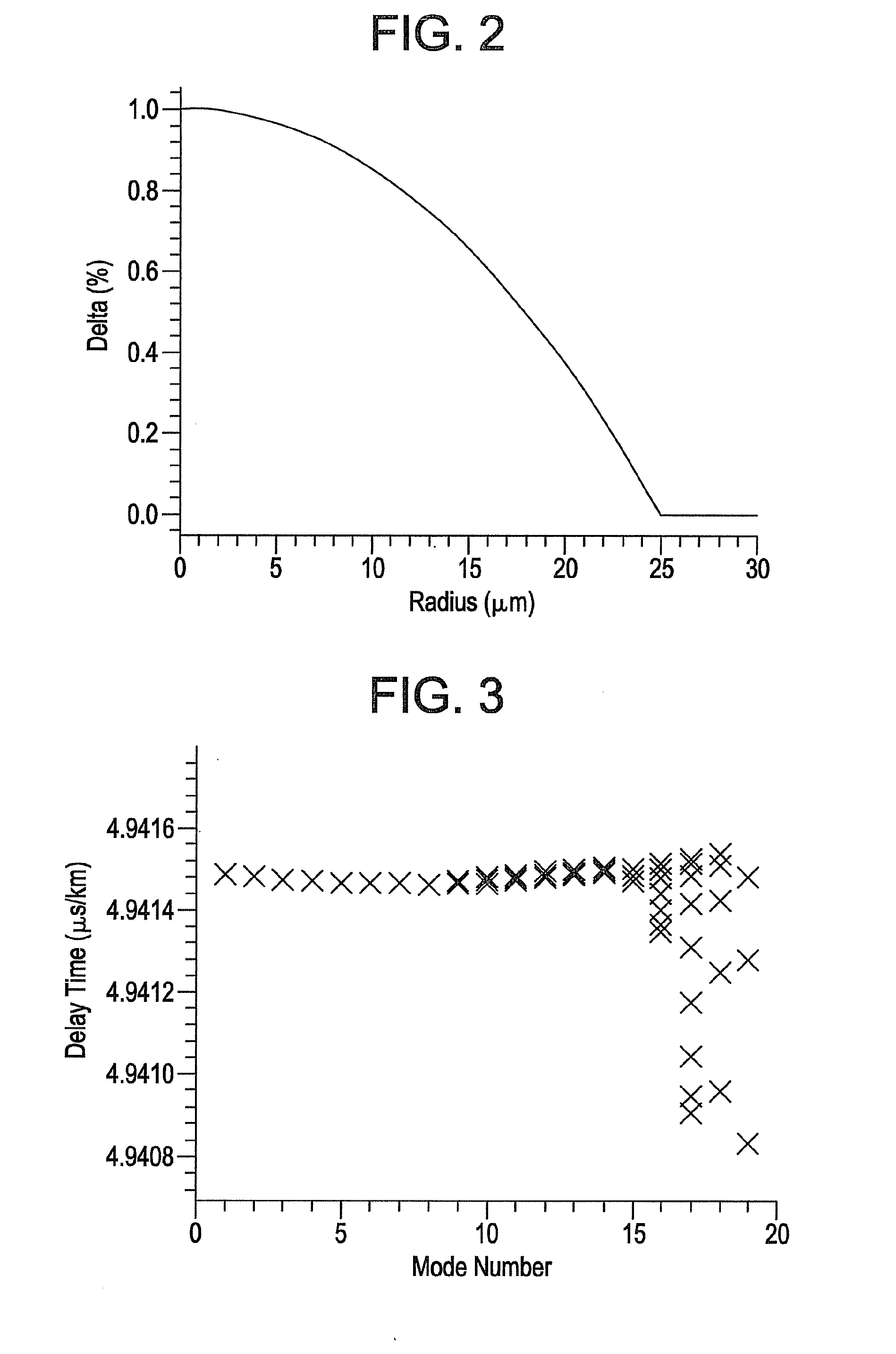
[0009]In the above-described aspects, the core region preferably has an alpha (α) between 1.8 and 2.5. In the above-described aspects, the optical fiber is preferably capable of guiding at least two mode groups at a wavelength of 850 nm, wherein the maximum differential delay between the fastest and slowest guided mode groups at a wavelength of 850 nm is less than 5 ns / km.

Problems solved by technology

In the past, these modes were not of particular concern because they had high loss as a result of perturbations such as bending and cladding absorption.
However, as fiber glass and coating technologies have improved, losses due to micro-bending and cladding absorption have reduced significantly.
As a result, some of the higher order modes can survive over the length of practical applications, which limits the multimode fiber bandwidth.

Method used


Image

  • Multimode Fiber With At Least Dual Cladding
  • Multimode Fiber With At Least Dual Cladding
  • Multimode Fiber With At Least Dual Cladding

Examples


example 1

[0055]FIG. 6 schematically illustrates a refractive index profile corresponding to an embodiment of the invention wherein the cladding is up-doped with GeO2 from a radius of 35 μm to the outermost edge of the cladding, wherein Δ3MAX is 0.2%, Δ2MIN is 0%, and the fiber contains no downdopants, such as fluorine. The differential mode delay time versus mode number for the optical fiber profile of FIG. 6 is illustrated in FIG. 7. The highest order modes (e.g., those with mode numbers from 16 to 19) each show a differential mode delay time that is limited to within about 0.12 ns / km.

example 2

[0056]FIG. 8 schematically illustrates a refractive index profile corresponding to an embodiment of the invention wherein the cladding is up-doped with GeO2 from a radius of 35 μm to a radius of 45 μm (i.e., a single up-doped ring), wherein Δ3MAX is 0.25%, Δ2MIN is 0%, and the fiber contains no downdopants, such as fluorine. This fiber index profile includes a diffused tail in the fiber core, which is a distortion from an ideal alpha profile. The differential mode delay time versus mode number for the optical fiber profile of FIG. 8 is illustrated in FIG. 9. The highest order modes (e.g., those with mode numbers from 16 to 19) each show a differential mode delay time that is less than 0.10 ns / km.

example 3

[0057]FIG. 10 schematically illustrates a refractive index profile corresponding to an embodiment of the invention wherein the cladding is up-doped with GeO2 from a radius of 35 μm to a radius of 45 μm and again from a radius of 50 μm to a radius of 60 μm (i.e., dual up-doped rings), wherein Δ3MAX is 0.25%, Δ2MIN is 0%, and the fiber contains no downdopants, such as fluorine. This fiber index profile includes a diffused tail in the fiber core, which is a distortion from an ideal alpha profile. The differential mode delay time versus mode number for the optical fiber profile of FIG. 10 is illustrated in FIG. 11. The highest order modes (e.g., those with mode numbers from 16 to 19) each show a differential mode delay time that is less than 0.10 ns / km.


PUM


Abstract

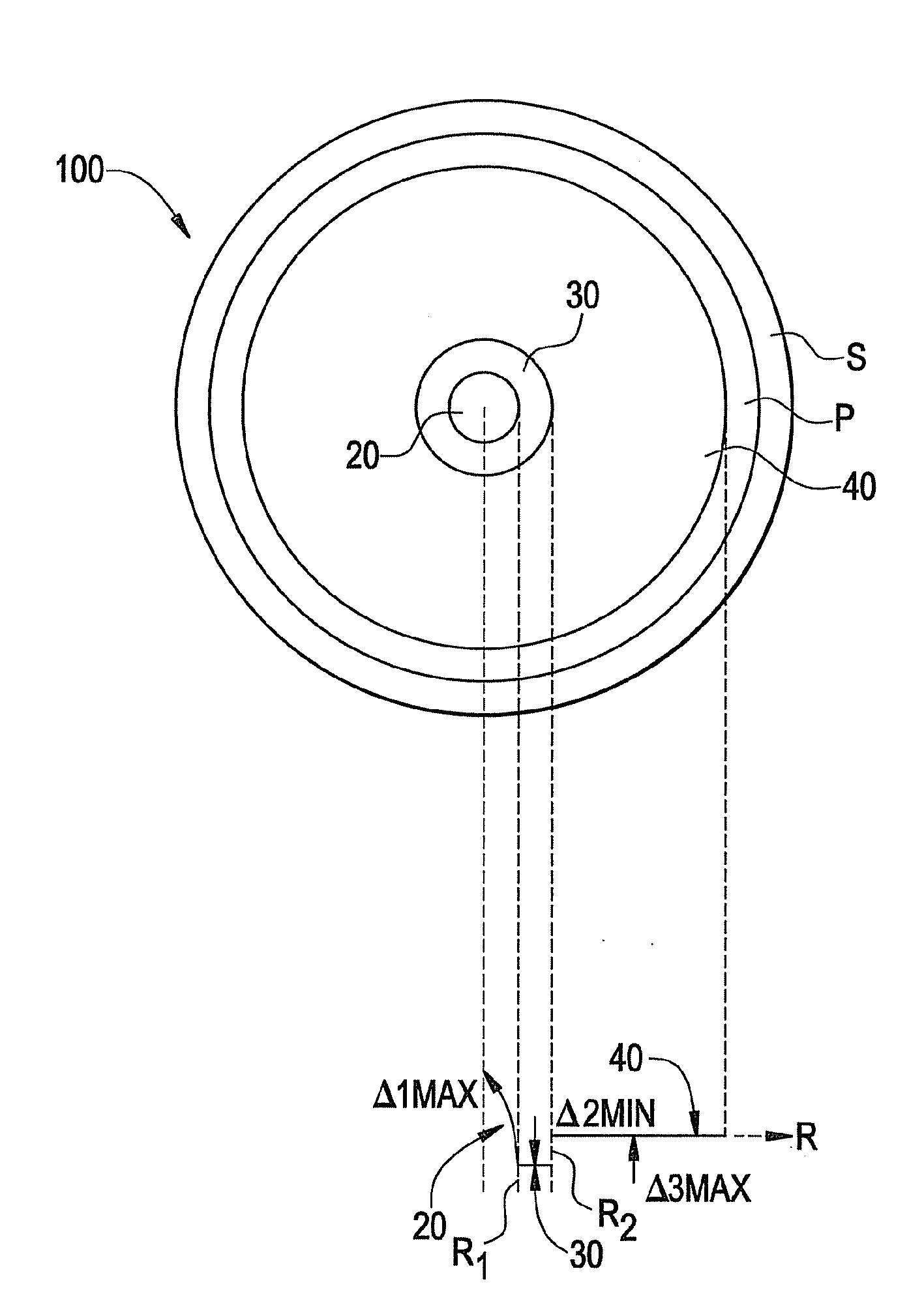
Multimode optical fiber is disclosed herein having a core surrounded by first and second annular cladding regions. The second annular cladding region has a maximum relative refractive index that is at least 0.05% higher than the minimum relative refractive index of the first annular cladding region.

Description

CROSS-REFERENCE To RELATED APPLICATIONS[0001]This application claims the benefit of, and priority to U.S. Provisional Patent Application No. 61 / 088,490 filed on Aug. 13, 2008 entitled, “Multimode Fiber with At Least Dual Cladding”, the content of which is relied upon and incorporated herein by reference in its entirety.BACKGROUND OF THE INVENTION [0002]1. Field of the Invention[0003]The present invention relates generally to optical fiber, and particularly to graded index multimode fibers.[0004]2. Technical Background[0005]The bandwidth of multimode fibers (MMF) is limited mostly by inter-modal chromatic dispersion. To minimize the inter-modal chromatic dispersion, MMF are designed with graded index α-profiles. For optimum bandwidth, the parameter α is about 2. However, a practical MNMh has a cladding that truncates the ideal alpha profile. For higher order modes near the cutoff frequency whose effective refractive index is close to that of the cladding, the time delay deviates from...

Claims


Application Information

Patent Timeline
Patent Type & Authority Applications(United States)
IPC IPC(8): G02B6/028
CPCG02B6/02214G02B6/0281G02B6/0288G02B6/03666G02B6/03644G02B6/03688G02B6/03627
Inventor CHEN, XINLI, MING-JUNNOLAN, DANIEL ALOYSIUS
Owner CORNING INC
Why Eureka
Try Eureka