Pseudo slant fiber bragg grating, multiple series fiber bragg grating, optical fiber type coupler and optical connector

a technology of multiple series and bragging, applied in the direction of optics, instruments, optical light guides, etc., can solve the problems of system trouble, wdm transmission system configuration simply and inexpensively, and inability to practice a high blocking quantity filter, etc., to achieve sufficient band blocking quantity, simple and inexpensive configuration of wdm transmission system, and high blocking quantity

Inactive Publication Date: 2006-03-30
SHOWA ELECTRIC WIRE & CABLE CO LTD
View PDF9 Cites 40 Cited by
  • Summary
  • Abstract
  • Description
  • Claims
  • Application Information

AI Technical Summary

Benefits of technology

[0019] These multiple series FBGs of the invention have a function to couple the multiplexly reflected light highly efficiently to the clad mode, and are enabled to improve the blocking characteristics better than the FBG or SFBG of the prior art by combining the coupling to the fundamental mode (backward) and the coupling to the clad mode.
[0021] According to the multiple series FBGs of the invention, the multiplexly reflected light can be transformed highly efficiently into the clad mode thereby to improve the blocking characteristics further.
[0023] According to the optical fiber type coupler of the invention, the COM port constructing the optical fiber type coupler includes the QSFBG or the multiple series FBG. Therefore, the coupler can retain a large blocking quantity and can construct the WDM transmission system simply and inexpensively.
[0025] According to the optical connector of the invention, on the other hand, the QSFBG of the invention or the multiple series FBG is packaged in the ferrule so that it is made into the plug type. It is, therefore, possible to retain the high blocking quantity and to connect the optical connector removably to another connector arranged in the optical transmission line thereby to configure the WDM transmission system simply and inexpensively. The optical connector can retain a sufficient band blocking quantity.

Problems solved by technology

Therefore, this system may be troubled under a severe temperature environment or may be changed in characteristics.
However, this system has failed to practice a filter of a high blocking quantity (e.g., 40 dB or more), for which needs have raised.
Still the worse, there is a difficulty that the degree of freedom for the system design cannot be improved.
In the low chirp rate FBG method of (1), however, the restriction on the accommodating space makes it difficult to retain a sufficient grating length, so that the practical chirp rate to be executed has a lower limit.
It is, however, difficult for the chirp rate necessary for the desired band (10 to 20 nm or more) to mass-produce the FBG having a blocking quantity of 40 dB or more.
For one chirped FBG (as will be called the “one-step FBG”), moreover, the reflection outside of the band near the Bragg wavelength is relatively high to raise a difficulty that the usable band is restricted.
In this system according to the SFBG, however, if the ordinary single mode fiber is employed, the coupling efficiency to the clad (or radiation) mode (as will be simply called the “clad mode”) is so low as to make it difficult to achieve a sufficient band blocking quantity.
In order to retain a large blocking quantity by the system using the SFBG, therefore, there arises a difficulty that a dedicated fiber having a low action to confine the signal light in the core, such as a fiber having a smaller specific refractive index difference (Δ) than the single mode fiber has to be employed.
Next, the two-step connection method (2) has a difficult that multiplex reflections (i.e., the Fabry-Perot resonance) occur between the two chirped FBGs.
As a result, the Fabry-Perot resonance occurs between the two FBGs to make a difficulty that a beat is generated in the spectral characteristics to lower the blocking characteristics.
However, this system is troubled by the narrowed usable band, as described hereinbefore.
In the case the reflections have to be positively caused at the FBG portion, that is, in the case the system is used with a view to blocking the line monitoring light, there arises a difficulty that the system cannot be employed because of a low reflection factor.

Method used


Image

  • Pseudo slant fiber bragg grating, multiple series fiber bragg grating, optical fiber type coupler and optical connector
  • Pseudo slant fiber bragg grating, multiple series fiber bragg grating, optical fiber type coupler and optical connector
  • Pseudo slant fiber bragg grating, multiple series fiber bragg grating, optical fiber type coupler and optical connector

Examples


first embodiment

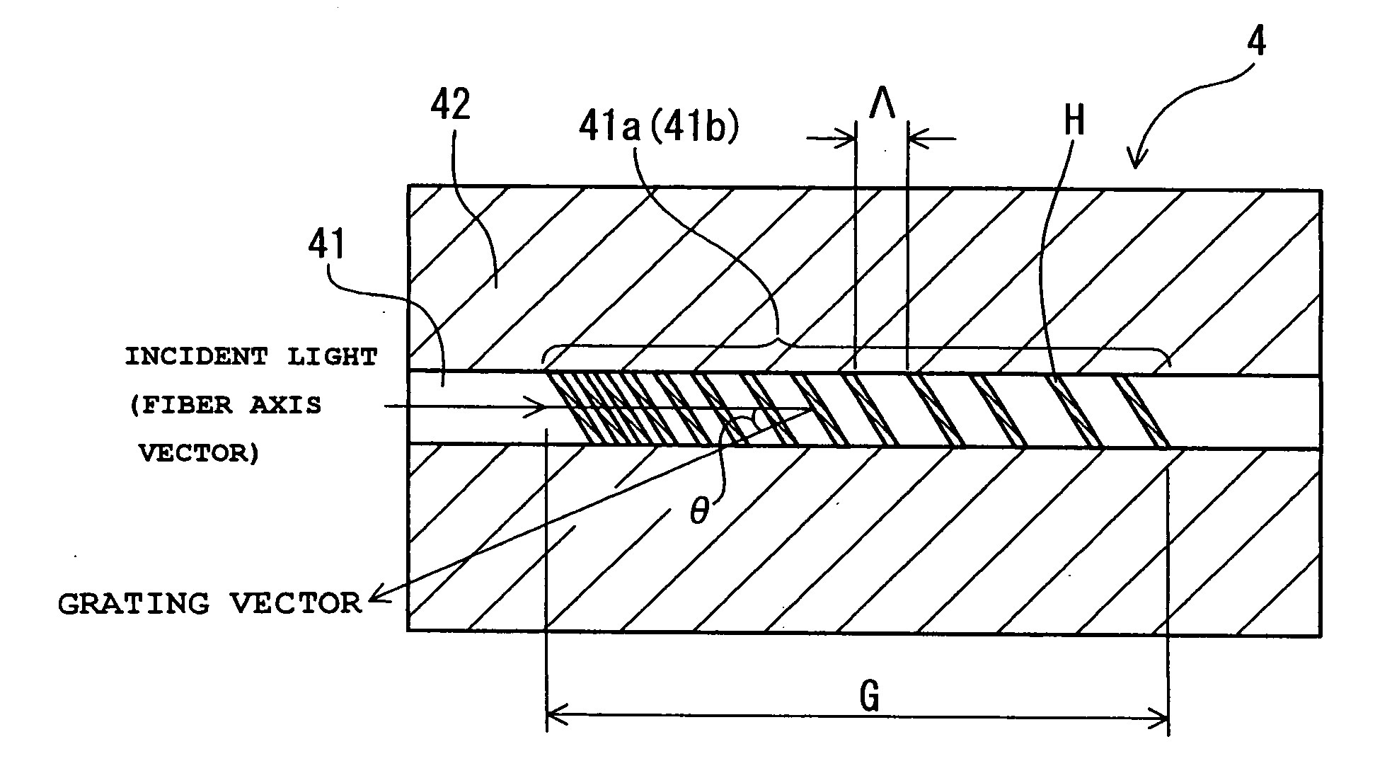
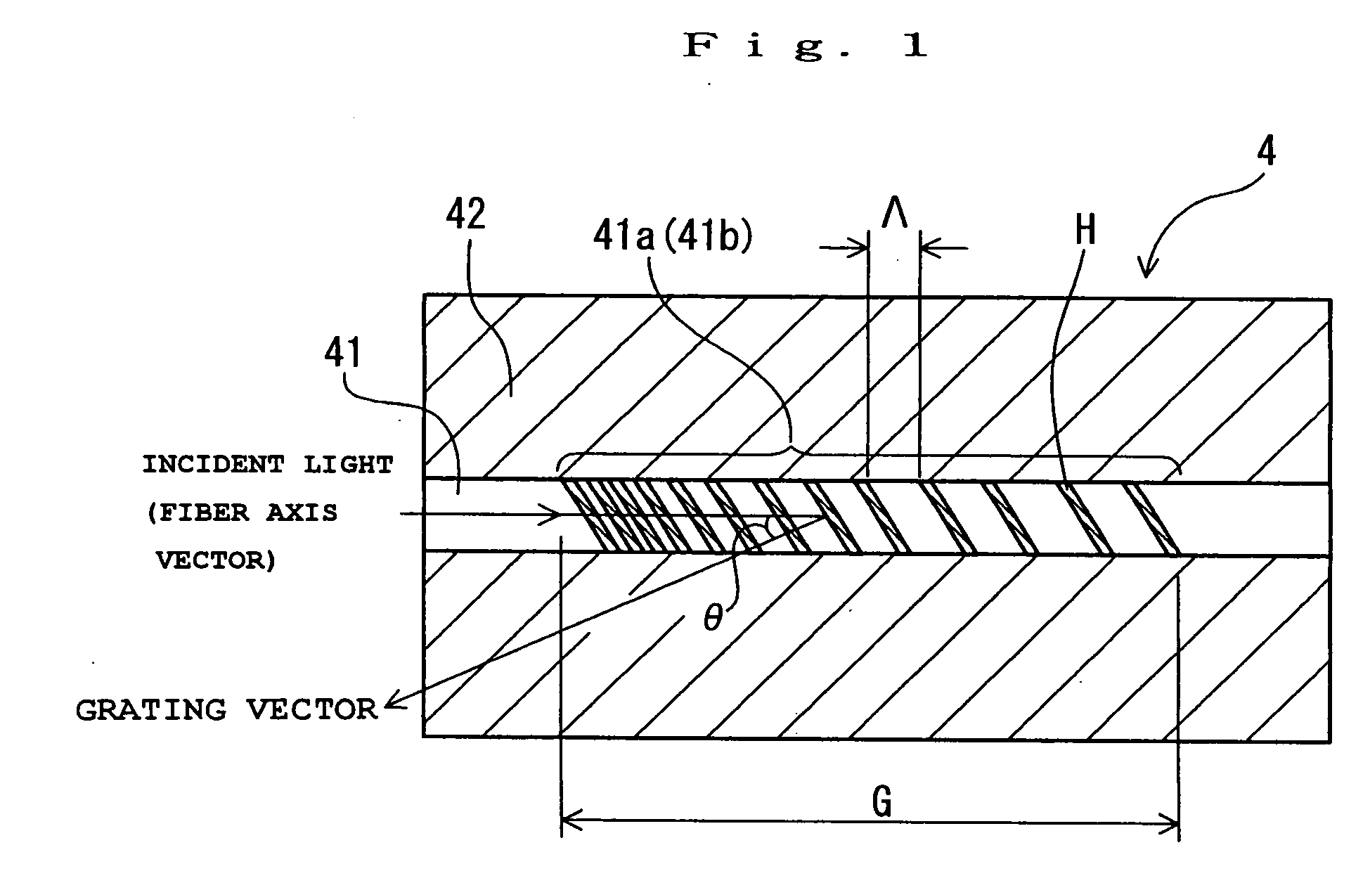
[0039]FIG. 1 is a longitudinal section of a QSFBG according to the invention. In FIG. 1, the QSFBG of the invention comprises an optical fiber 4 including a core 41 composed mainly of quartz glass, and a clad 42 formed on the outer circumference of the core 41 and having a smaller refractive index than that of the core 41. In this core 41, a first refractive index grating portion 41a or a second refractive index grating portion 41b is made such that the grating gap gradually varies along an optical axis and such that the grating vector slopes with respect to the fiber primary axis. Specifically, the phase mask (not-shown) is so arranged on the outer side of the optical fiber 4 as to slope with respect to the axis of the optical fiber 4, and this phase mask is irradiated from the outside with the ultraviolet ray (not-shown). As a result, the first refractive index grating portion 41a or the second refractive index grating portion 41b is formed at such a predetermined portion of the c...

second embodiment

[0054] Specifically, the multiple series FBG thus far described is manufactured in the following specific procedure.

[0055] Specifically, the optical fiber 4 having a clad diameter of 125 μm was made by adding Ge to the core 41 having a core diameter of 8 μm and a relative refractive index difference of 0.3%, and the QSFBGs of the first kind and the second kind (i.e., the first and second refractive index grating portions 41a and 41b) having a slant angle (θ) of 2° were formed in series in the optical fiber 4 by the phase mask method using KrF excimer laser (λ=248 nm). Here, the central period (2Λ) of the plasma mask of a chirped grating is 1,140 nm, the chip rate (C) of the period is 1.2 nm / mm, the length (G) of the QSFBGs of the first kind and the second kind (i.e., the first and second index grating portions 41a and 41b) is 8 mm, the effective refractive index (N) of the QSFBGs of the first kind and the second kind (i.e., the first and second index grating portions 41a and 41b) i...


PUM


Abstract

An optical fiber 4 having a clad diameter of 125 μm is made by adding Ge to a core 41 having a core diameter of 8 μm and a relative refractive index difference of 0.3 %, and two refractive index grating portions 41a and 41b having a slant angle of 2° are formed in series in the optical fiber 4 by a phase mask method using KrF excimer laser (λ=248 nm). The central period (2Λ) of the phase mask of a chirped grating is 1,140 nm, the chip rate (C) of the period is 1.2 nm / mm, the length (G) of the first and second index grating portions 41a and 41b is 8 mm, the effective refractive index of the first and second index grating portions 41a and 41b is 1.447, the refractive index modulation is 3×10⁻³, and the gap between the first and second index grating portions 41a and 41b is 1 mm.

Description

TECHNICAL FIELD [0001] The present invention relates to a quasi slanted fiber Bragg grating, a multiple series Bragg grating, an optical fiber type coupler and an optical connector and, more particularly, to a quasi slanted fiber Bragg grating, a multiple series Bragg grating, an optical fiber type coupler and an optical connector, which are useful in a WDM (Wavelength Division Multiplexing) transmission system for separating desired signal light from a superposed signal group or the like. BACKGROUND ART [0002] In recent years, the WDM transmission system has been noted as a system for transmitting a mass volume of information. This WDM transmission system transmits signal light or test light of plural wavelengths multiplexly through one optical fiber. The transmission side has to use an optical coupler for composing the individual signal light and test light, and the reception side has to use an optical divider for dividing the individual signal light and an optical blocking filter...

Claims


Application Information

Patent Timeline
Patent Type & Authority Applications(United States)
IPC IPC(8): G02B6/34G02B6/38G02B6/42
CPCG02B6/02085G02B6/02138G02B6/3826G02B6/4246G02B6/3846G02B6/3893G02B6/3845
Inventor KANJI, SHISHIDOHIROSHI, ISHIKAWAMASAHIRO, NAKAMURAKAZUAKI, MORITA
Owner SHOWA ELECTRIC WIRE & CABLE CO LTD
Why Eureka
Try Eureka