Single-mode optical fiber, optical fiber cable, optical fiber cord, and method for ensuring service life of optical fiber

a single-mode optical fiber and service life technology, applied in the field of single-mode optical fiber, can solve the problems of cable breaking in only a matter of few years, and gradual extension of cracks on the surface of optical fiber

Inactive Publication Date: 2006-06-01
THE FUJIKURA CABLE WORKS LTD
View PDF1 Cites 41 Cited by
  • Summary
  • Abstract
  • Description
  • Claims
  • Application Information

AI Technical Summary

Benefits of technology

[0007] Another exemplary embodiment of the present invention provides a method for ensuring a service life of above-described single-mode optical fiber, or of a single-mode optical fiber used in an optical fiber cable or of a single-mode optical fiber used in an optical fiber cord according to the present invention. The method includes measuring a loss in the longitudinal direction of the single-mode optical fiber that is laid using an optical time domain reflectometer (OTDR) technique or by measuring a transmission loss in the entire length of the single-mode optical fiber, and ensuring that a failure probability of the single-mode optical fiber during a predetermined service life falls within a failure probability used for setting a limit bending radius by confirming that the measured loss is smaller than a beading loss that is generated when a bend having a bending radius smaller than the limit bending radius is applied to the single-mode optical fiber.

Problems solved by technology

It has bee know that when an optical fiber that is designed for use in a typical transmission path is used while it is bent in a small bending radius, cracks present on the surface of the optical fiber gradually extends due to a phenomenon called fatigue, and the optical fiber may be broken after a certain time period.
However, when an optical fiber is bent to an extremely small radius, the cable may be broken in only a matter of few years.

Method used


Image

  • Single-mode optical fiber, optical fiber cable, optical fiber cord, and method for ensuring service life of optical fiber
  • Single-mode optical fiber, optical fiber cable, optical fiber cord, and method for ensuring service life of optical fiber
  • Single-mode optical fiber, optical fiber cable, optical fiber cord, and method for ensuring service life of optical fiber

Examples


example

Example 1

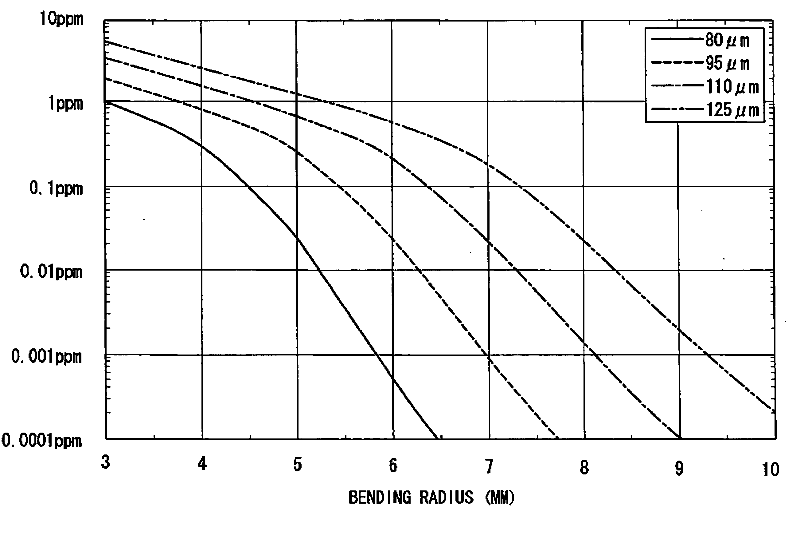
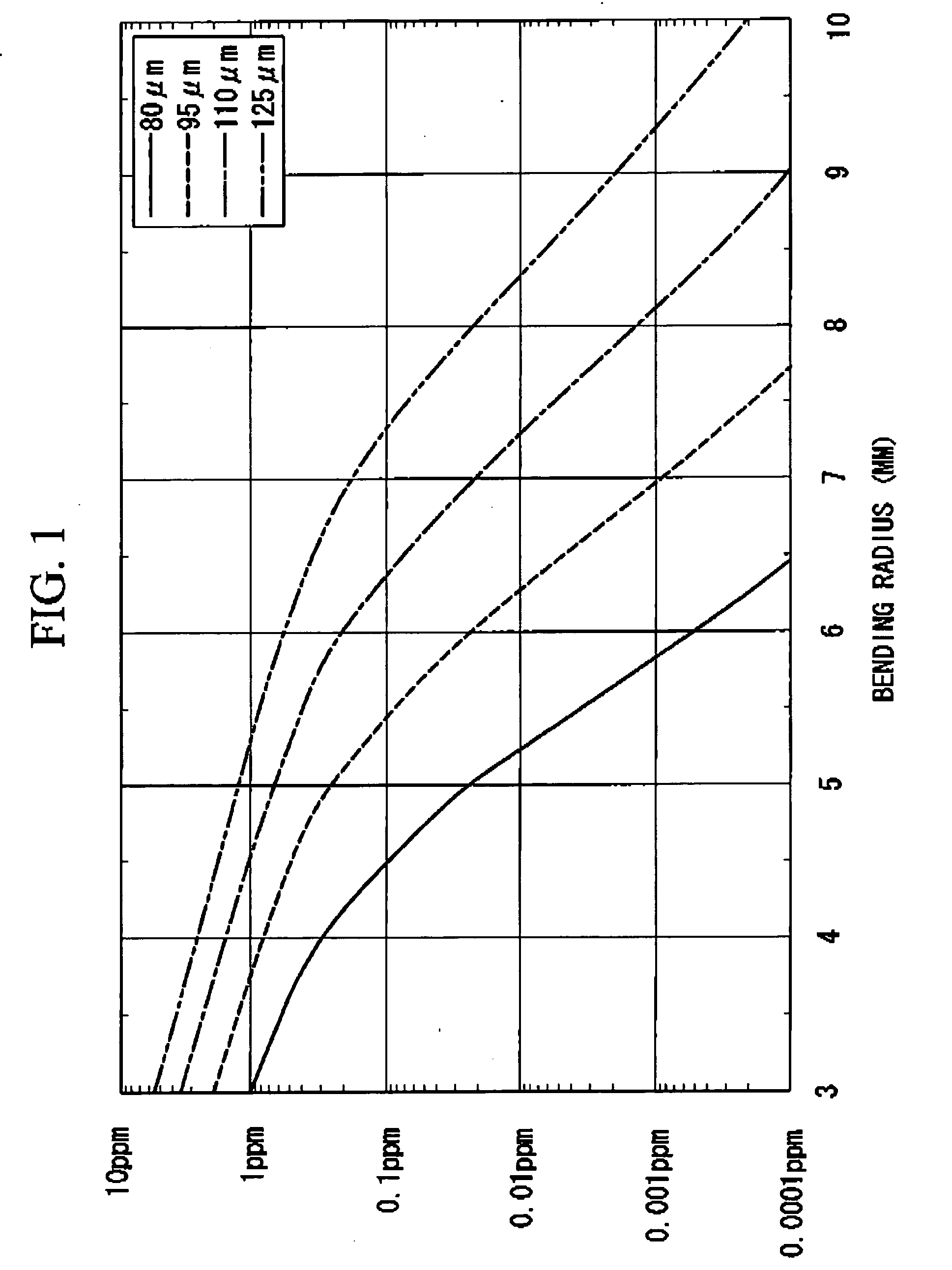
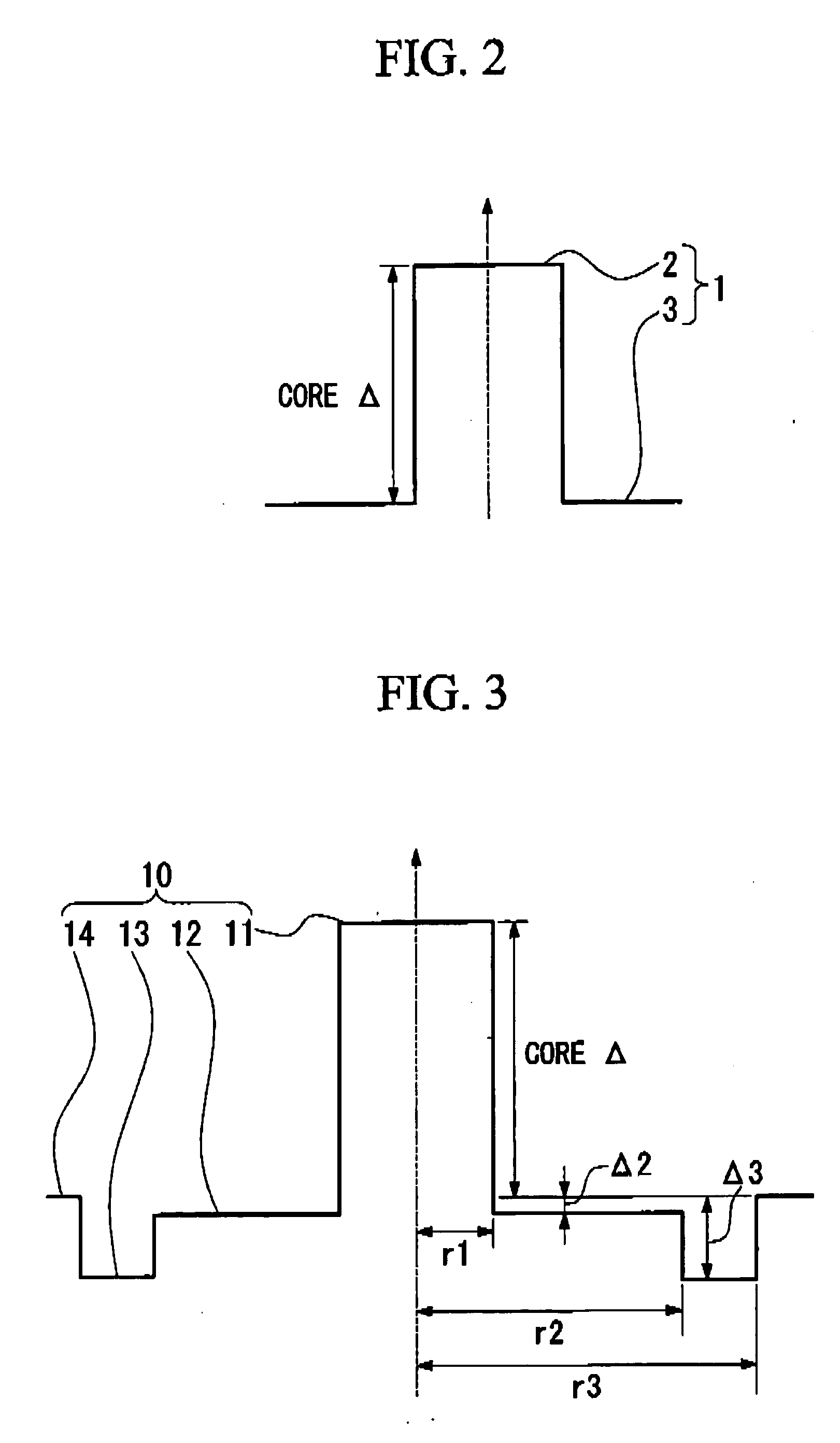
[0035] In an optical fiber 1 that has typical step index type refractive index profile as in FIG. 2 and a cladding diameter of 125 μm and a fiber cut-off of 1.26 mm, the mode field diameter and the bending loss were calculated while varying the core Δ, which is the relative refractive index difference of the core 2 with respect to the cladding 3. The results are listed in Table 1.

TABLE 1OpticalcharacteristicsMeasure-Core ΔCut-offmentUnit0.35%0.40%0.50%0.55%0.70%0.75%0.80%0.85%0.90%wavelengthwavelengthμm1.261.261.261.261.261.261.261.261.26Mode field1.31 μmμm9.18.57.57.26.36.15.95.75.6diameter1.55 μmμm10.29.68.58.17.26.96.76.56.3Bending loss at1.55 μmdB / turn10616 × 10−14 × 10−21 × 10−20.5 × 10−20.2 × 10−20.1 × 10⁻²bending radius ofor less5.5 mmBending loss at1.625 μm dB / turn1810312 × 10−15 × 10−2  3 × 10⁻²  1 × 10−20.4 × 10−3beading radius of5.5 mm

[0036] When the service life of the optical fiber is assumed to be 20 years and the failure probability is assumed to be 1 ppm ...

example 2

[0042] Another example was studied using an optical fiber 10 having a trench refractive index profile as in FIG. 3. In this example, the following parameters were used: the radius of the central core region 11 was r1, the radius of the inner cladding region 12 was r2, the radius of the trench portion 13 that is provided around the outer periphery of the inner cladding region 12 and has lower refractive index than that of the inner cladding region 12 was r3, and the relative refractive index difference of the central core region 11 with respect to the cladding 14 was used as a core Δ. The relative refractive index difference of the inner cladding region 12 was Δ2 and the relative refractive index difference of the trench portion 13 was Δ3. A single-mode optical fiber having a cladding diameter of 125 μm was designed so tat the fiber cutoff was 1.26 μm, r2 / r1 was 3.5, r3 / r1 was 5.5, Δ2 was 0%, Δ3 was −0.250%, and the mode field diameter and the bending loss were calculated while varyi...


PUM


Abstract

A single-mode optical fiber, cable, cord, and a method for ensuring a service life of the fiber are provided. The fiber has a core and a cladding, the fiber having a cut-off wavelength that exhibits a single-mode transmission in a 1.31 μm wavelength band. A relative refractive index difference of the core with respect to the cladding is adjusted such that a bending loss, when a bend is applied in a radius smaller than a limit bending radius of the fiber, becomes greater than a detection limit value. The limit bending radius is calculated from a relationship between a bending radius applied to the optical fiber and a failure probability which occurs after a time period. The method includes measuring a loss and ensuring that a failure probability of the fiber during a service life falls within a failure probability used for setting the limit bending radius.

Description

CROSS-REFERENCE TO RELATED APPLICATIONS [0001] Priority is claimed from Japanese Patent Application No. 2004 346053, filed Nov. 30, 2004, the content of which is incorporated herein by reference. BACKGROUND OF THE INVENTION [0002] In recent years, optical fibers having a low transmission loss caused by a bend (bending loss) have been developed in light of ease of manufacturing and ease of laying cables. Optical fibers are known which have a transmission loss of about 0.0008 dB / turn even when they are bent to a bending radius of about 2.5 mm, for example, so that they can be employed in a small bending radius, and such optical fibers can be used even when they are bent to a extremely small radius at an early stage after the installation (see, for example, Daizo Nishioka, et al., Development of a Holey Fiber with Ultra-low Bending Loss, Technical Report of IEICE, OFT2003-63; Bing Yao, et al., Development of Holey Fibers, Technical Report of IEICE, OFT2003-27). [0003] It has bee know t...

Claims


Application Information

Patent Timeline
Patent Type & Authority Applications(United States)
IPC IPC(8): G02B6/02
CPCG02B6/02G02B6/0365
Inventor KUTAMI, HIROSHIMATSUO, SHOICHIROHIMENO, KUNIHARU
Owner THE FUJIKURA CABLE WORKS LTD
Why Eureka
Try Eureka