Touch pen for a capacitive touch pad

a capacitive touch pad and touch pen technology, applied in the field of touch pen, can solve the problems that the pressure sensor b>13/b> is easily affected by failure, and achieve the effect of reducing the failure probability and avoiding perplexing the user

Inactive Publication Date: 2016-09-13
PRIMAX ELECTRONICS LTD
View PDF6 Cites 0 Cited by
  • Summary
  • Abstract
  • Description
  • Claims
  • Application Information

AI Technical Summary

Benefits of technology

[0011]An object of the present invention provides a touch pen for reducing the failure probability and avoiding perplexing the user.
[0013]From the above descriptions, the present invention provides the touch pen. The buffering element is arranged between the contact element and the sensing device. The contact element and the sensing device are separated from each other by the buffering element. If the external force applied to the touch pen is very large and the contact element is moved relative to the sleeve in the direction toward the sensing device, the impact of the contact element on the sensing device is largely reduced because the contact element and the sensing device are separated from each other by the buffering element. Moreover, since the external force is received by the buffering element, the sensing device can be protected by the buffering element. Moreover, once the buffering elastic force of the buffering element is released, the contact element is returned to the original position. Consequently, the failure probability of the touch pen is reduced. Since the buffering element has a transmission pin and connected with the circuit board of the sensing device, after the touch signal is generated by the controlling unit, the touch signal may be transmitted to the capacitive touch pad through the circuit board, the transmission pin and the contact element. That is, in addition to the function of separating the contact element from the sensing device, the buffering element further has the function of transmitting the touch signal. Moreover, since the touch pen of the present invention further comprises the calibration element for continuously pushing the sensing device, the sensing element may be considered as a linear element. Consequently, the magnitude of the pressing force for operating the touch pen can be easily controlled by the user.

Problems solved by technology

Firstly, due to the structure of the conventional capacitive touch pen 1, the pressure sensor 13 is readily suffered from failure.

Method used


Image

  • Touch pen for a capacitive touch pad
  • Touch pen for a capacitive touch pad
  • Touch pen for a capacitive touch pad

Examples


Embodiment Construction

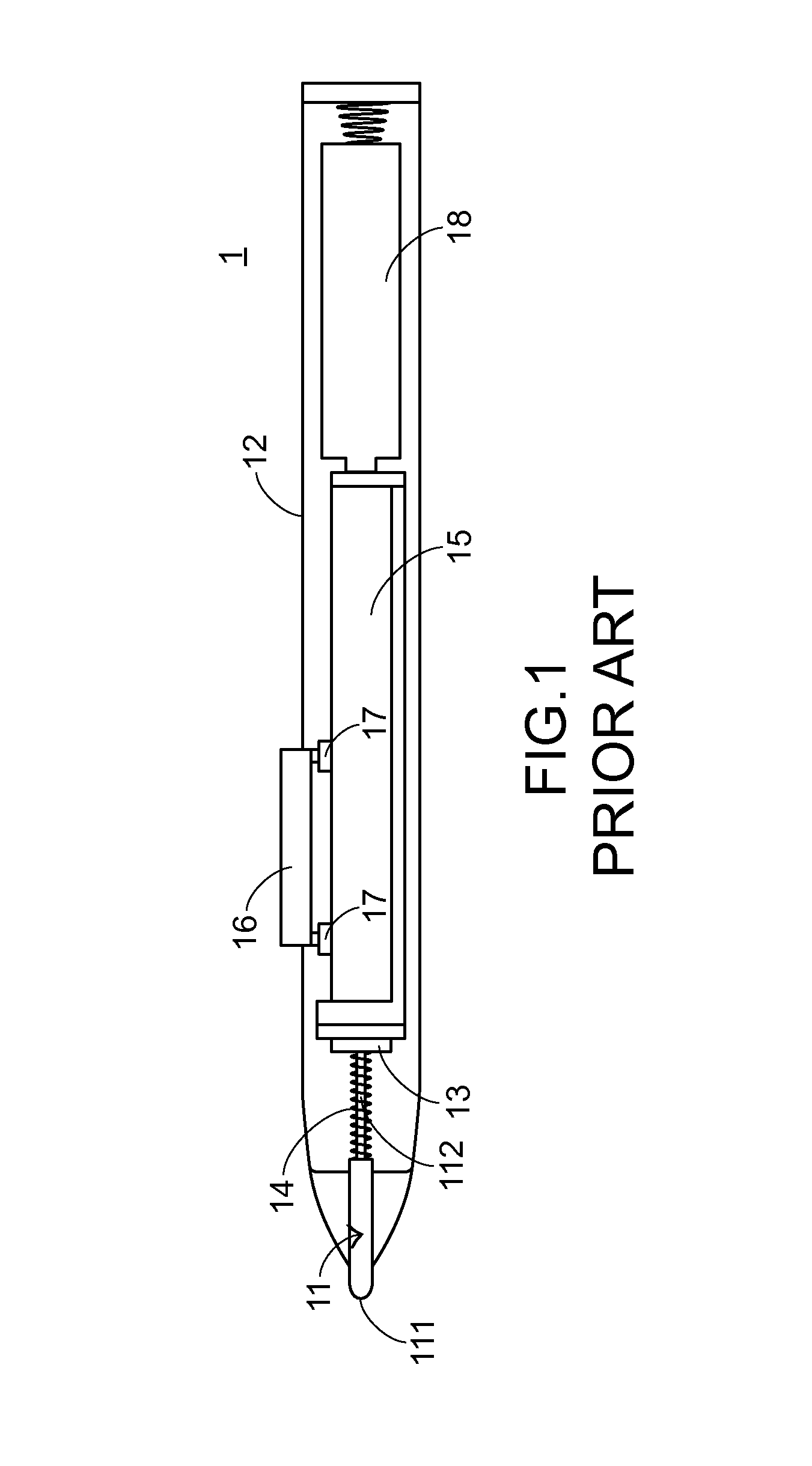
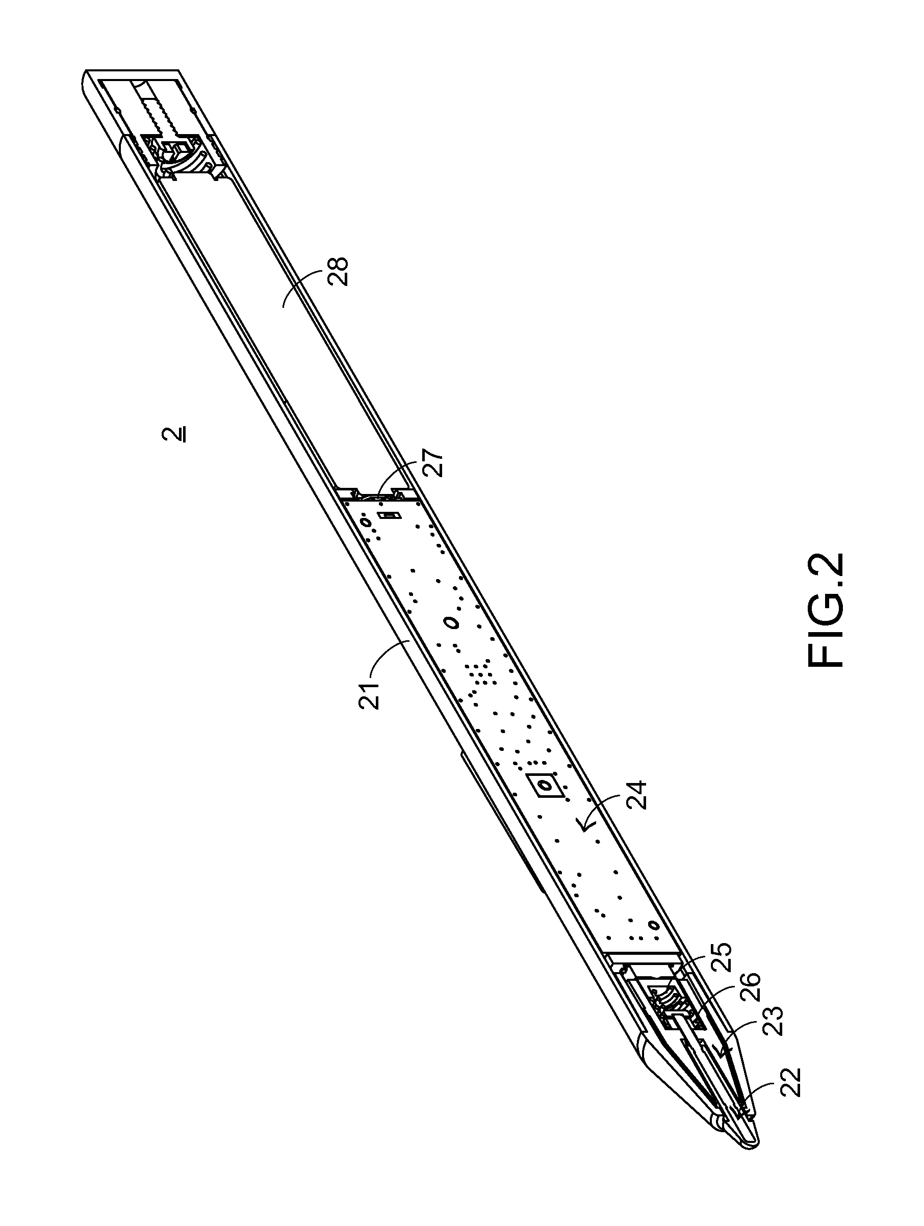
[0021]For solving the drawbacks of the conventional technology, the present invention provides a touch pen. Hereinafter, the structure of a touch pen will be illustrated with reference to FIGS. 2 and 3. FIG. 2 is a schematic cross-sectional view illustrating a touch pen according to an embodiment of the present invention. FIG. 3 is a schematic exploded view illustrating a portion of the touch pen according to the embodiment of the present invention. The touch pen 2 is used for controlling a capacitive touch pad (not shown). In this embodiment, the touch pen 2 comprises a main body 21, a contact element 22, a sleeve 23, a sensing device 24, a buffering element 25, a calibration element 26, a conductive part 27 and a battery 28. The contact element 22 is disposed on the main body 21 and partially protruded out of the main body 21. When the contact element 22 is contacted with the capacitive touch pad, the sensing device 24 is triggered to generate a touch signal and the touch signal i...


PUM


Abstract

A touch pen includes a sleeve, a contact element, a sensing device and a buffering element. The contact element is penetrated through the sleeve and movably relative to the sleeve. The sensing device is disposed within the sleeve. The buffering element is disposed within the sleeve. The contact element and the sensing device are separated from each other by the buffering element. While the contact element is moved in response to an external force applied to touch pen, the impact of the contact element on the sensing device is largely reduced because the contact element and the sensing device are separated from each other by the buffering element. Moreover, since the external force is received by the buffering element, the sensing device can be protected by the buffering element. Consequently, the failure probability of the touch pen is reduced.

Description

FIELD OF THE INVENTION[0001]The present invention relates to a touch pen, and more particularly to a touch pen for a capacitive touch pad.BACKGROUND OF THE INVENTION[0002]The widely-used peripheral input device of a computer system comprises for example a mouse device, a keyboard device, a trackball device, or the like. With the progress of the times, a touch pad has been introduced into the market. By directly using the user's fingers or using a touch pen to operate the touch input device, the computer system or other appropriate electronic device can be correspondingly controlled.[0003]Nowadays, the commercially available touch pads are classified into several types, including a resistive touch pad, an acoustic wave touch pad, an infrared touch pad and a capacitive touch pad. The operating principles of these touch pads will be shortly illustrated. When a pressing object (e.g. the user's finger) is placed on the resistive touch pad, a voltage is generated and the pressing position...

Claims


Application Information

Patent Timeline
Patent Type & Authority Patents(United States)
IPC IPC(8): G06F3/0354G06F3/041G06F3/044
CPCG06F3/03545G06F3/0416G06F3/044
Inventor CHAN, CHIN-PINGHSU, CHENG-CHI
Owner PRIMAX ELECTRONICS LTD
Why Eureka
Try Eureka