Method for supporting MPLS transport path recovery with multiple protection entities

a protection entity and transport path technology, applied in the field of telecommunications, can solve the problems of connection drop, existing mpls-tp linear protection mechanism may not meet operator availability requirements, etc., and achieve the effect of minimizing a cost function

Active Publication Date: 2014-09-09
ORCKIT CORP
View PDF7 Cites 0 Cited by
  • Summary
  • Abstract
  • Description
  • Claims
  • Application Information

AI Technical Summary

Benefits of technology

[0008]The method of the first aspect may further include the steps of selecting a working entity from the plurality of transport entities, selecting a protection entity from the plurality of transport entities, and selecting an active entity from the set consisting of the working entity and the protection entity, wherein selecting an entity further includes minimizing a cost function. The cost function may include minimizing a probability of concurrent failure of the protection entity and the working entity. The cost function may further incorporate a predefined metric, such as IGP and / or TE.

Problems solved by technology

However, if the disruption is more prolonged, connections may drop.
However, in network environments where span or node failure likelihood is relatively high, existing MPLS-TP linear protection mechanisms may not meet operator availability requirements since they may not protect against one or several failures affecting both the working entity and the protection entity.

Method used


Image

  • Method for supporting MPLS transport path recovery with multiple protection entities
  • Method for supporting MPLS transport path recovery with multiple protection entities
  • Method for supporting MPLS transport path recovery with multiple protection entities

Examples


first embodiment

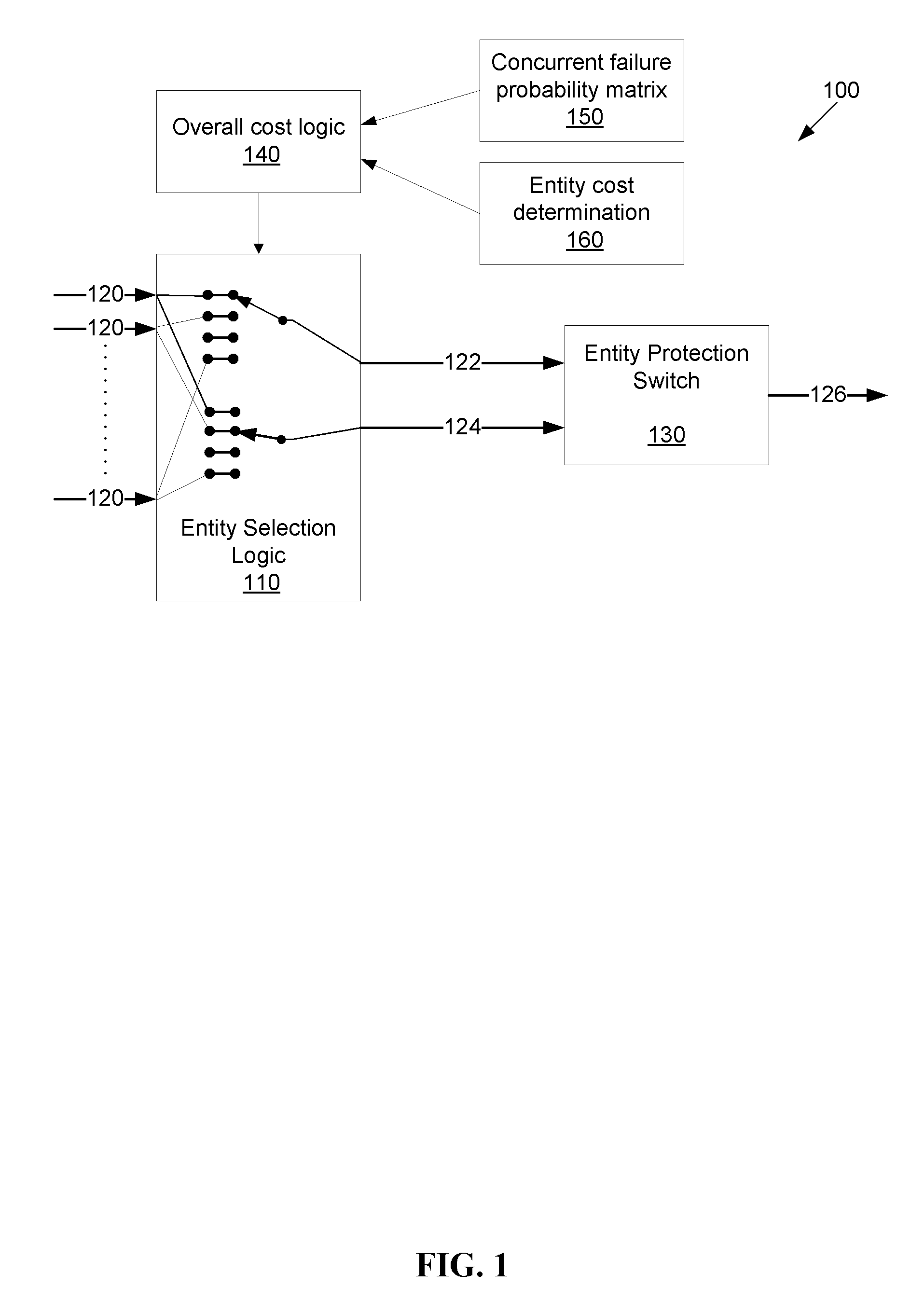
[0022]A first exemplary embodiment of an entity protection system 100 is shown in FIG. 1. The first embodiment for executing the functionality may be a computer, as described below. An entity protection switch 130 switches between a working entity 122 and a protection entity 124 from a set of entities 120 or entity descriptors represented within an entity selection logic block 110. Each entity 120 represents a network route between a first endpoint and a second endpoint, and may include entity cost data associated with each entity, for example, interior gateway protocol (IGP) data, traffic engineering (TE) data, and probability of entity failure. An overall cost logic block 140 uses results from a concurrent failure probability matrix 150 and an entity cost determination block 160 to select the working entity 122 and the protection entity 124 from the set of entities 120, as described below. The concurrent failure probability matrix 150 examines the set of entities 120 and calculate...

second embodiment

[0032]overall cost minimization shown in FIG. 4B, minimizes entity cost according to one or more predefined metrics (block 450), for example, interior gateway protocol (IGP) or traffic engineering (TE) data, for the selected working entity. When network efficiency optimization is desired, the MPLS linear protection block may be configured to be revertive, and therefore, in the absence of entity failures, the working entity will be active.

[0033]Since the first overall cost minimizing embodiment and the second overall cost minimizing embodiment may produce conflicting results, a third overall cost minimizing entity selection embodiment, shown in FIG. 4C, may minimize an operator-defined function of the simultaneous failure probability (SFP) and the entity cost. An example of this function would be to minimize SFP (block 410) by selecting working and protection entity pairs with the lowest SFP, and, if there are multiple pairs with the same SFP within an error margin, as shown by block...


PUM


Abstract

A system and method for selecting MPLS network transport entities between a first endpoint and a second endpoint are presented. Working and protection entities are selected from a set of available entities based upon minimizing the probability of simultaneous failure and / or minimizing a cost function base upon one or more metrics.

Description

CROSS-REFERENCE TO RELATED APPLICATIONS[0001]This application claims the benefit of U.S. Provisional Patent Application Ser. No. 61 / 499,943, filed Jun. 22, 2011, entitled “Method for Supporting MPLS Transport Path Recovery with Multiple Protection Paths,” which is incorporated by reference herein in its entirety.FIELD OF THE INVENTION[0002]The present invention relates to telecommunications and more particularly, is related to high availability of telecommunication entities.BACKGROUND OF THE INVENTION[0003]Availability of network connections has been the focus of increasing interest in the telecommunications field. In particular, the practice of maintaining redundant network devices and connections has become commonplace. Under the practice of redundancy, when a failure is detected in a network device or connection, network traffic is switched to a standby network device or connection. While some data may be lost in the switch-over process, most network protocols, for example TCP / IP...

Claims


Application Information

Patent Timeline
Patent Type & Authority Patents(United States)
IPC IPC(8): H04J1/16H04L12/28H04L45/586H04L45/28H04L45/50H04L69/40
CPCH04J3/14H04L45/12H04L45/22H04L45/28H04L45/50H04L1/22H04L69/40
Inventor COHN, DANIELRAM, RAFI
Owner ORCKIT CORP
Why Eureka
Try Eureka