
Pressure generation apparatus and method for superconducting power equipment

a superconducting power equipment and pressure generation technology, applied in the direction of superconducting magnets/coils, domestic cooling devices, magnetic bodies, etc., can solve the problems of resistance, superconductivity loss, dielectric breakdown of superconducting fault current limiters, etc., to reduce the failure probability of the pressure system, simplify the pressure system, and minimize the effect of superconducting power equipmen

Active Publication Date: 2021-08-10
KOREA ELECTRIC POWER CORP
View PDF9 Cites 0 Cited by
  • Summary
  • Abstract
  • Description
  • Claims
  • Application Information

AI Technical Summary

Benefits of technology

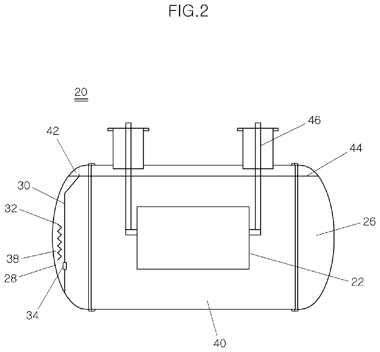
[0037]According to the present invention, it is possible to achieve miniaturization of superconducting power equipment by enabling a pressure system separately arranged outside a pressure vessel to apply pressure to liquid nitrogen in the superconducting power equipment to be disposed inside a pressure vessel, thereby reducing the installation area of pressure tanks, cooling pipes, gas piping, valves, and the like that constitute the pressure system in the related art.
[0038]In addition, since there is no valve for flow of the liquid nitrogen from the existing pressure tank into the pressure vessel so that it is not necessary to control the valve, there is an effect that the pressure system can be simplified.
[0039]Accordingly, there is an effect that the failure probability of the pressure system is reduced and the performance of the superconducting power equipment is made uniform by above-described configuration, thereby increasing reliability and contributing to stable power system operation.
[0040]In addition, according to the above-described effects, there is an effect that it is possible to contribute to the expansion and spreading of various superconducting power equipment.

Problems solved by technology

In particular, when the electric current density is higher than the threshold current density, superconductivity is lost and resistance appears.
Since the insulating properties of gaseous nitrogen are only a fraction of the liquid nitrogen, bubble formation due to liquid nitrogen vaporization during quenching can lead to dielectric breakdown of the superconducting fault current limiter.
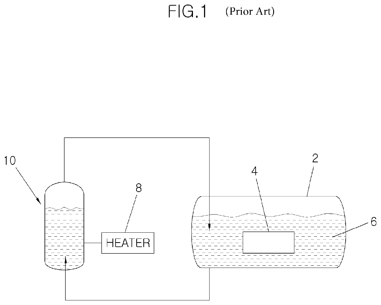
In such a structure, it is necessary to provide the refrigerant storage part 10 outside the pressure vessel 2, arrange a pipe connecting the pressure vessel 2 and the refrigerant storage part 10, provide a valve for supplying liquid and a controller, and so on, whereby there is a problem that the system is complicated and the installation area is also increased.

Method used


Image

  • Pressure generation apparatus and method for superconducting power equipment
  • Pressure generation apparatus and method for superconducting power equipment
  • Pressure generation apparatus and method for superconducting power equipment

Examples


Embodiment Construction

[0045]For a better understanding of the present invention, a preferred embodiment of the present invention will be described with reference to the accompanying drawings. The embodiments of the present invention can be modified in various forms, and the scope of the present invention should not be construed as being limited to the embodiments described in detail below. The present embodiments are provided to enable those skilled in the art to more fully understand the present invention. Therefore, the shapes and the like of the elements in the drawings can be exaggeratedly expressed to emphasize a clearer description. It should be noted that the same components are denoted by the same reference numerals in the drawings. Detailed descriptions of well-known functions and constructions which may be unnecessarily obscured by the gist of the present invention are omitted.

[0046]The present invention relates to pressure generation apparatus and method for superconducting power equipment in ...


PUM

PropertyMeasurementUnit
temperatureaaaaaaaaaa
pressureaaaaaaaaaa
shapeaaaaaaaaaa

Abstract

The present invention relates to pressure generation apparatus and method for superconducting power equipment and, more particularly, to pressure generation apparatus and method for superconducting power equipment, wherein a pressure system separately arranged to apply pressure to liquid nitrogen in the superconducting power equipment is disposed inside a pressure vessel.

Description

CROSS REFERENCE TO RELATED PATENT APPLICATION[0001]This application claims the benefit under 35 U.S.C. Section 371, of PCT International Application No. PCT / KR2016 / 013554, filed on Nov. 23, 2016, which claimed priority to Korean Patent Application No. KR 10-2016-0121622, filed on Sep. 22, 2016, the disclosures of which are hereby incorporated by the references.TECHNICAL FIELD[0002]The present invention relates to pressure generation apparatus and method for superconducting power equipment and, more particularly, to pressure generation apparatus and method for superconducting power equipment, in which a pressure system separately arranged to apply pressure to liquid nitrogen in superconducting power equipment is disposed inside a pressure vessel.BACKGROUND ART[0003]Generally, superconductivity refers to a phenomenon in which certain materials have zero electrical resistance and exhibit a completely semi-magnetic property in a specific condition (temperature, current density, magnetic...

Claims


Application Information

Patent Timeline
Patent Type & Authority Patents(United States)
IPC IPC(8): F25D17/02H01B12/16H01F6/04H01F6/00H02H9/02
CPCH02H9/023F25D17/02H01B12/16H01F6/04H01F2006/001Y02E40/60H01F6/00H01F36/00
Inventor HAN, YOUNG-HEEPARK, BYUNG-JUNYANG, SEONG-EUN
Owner KOREA ELECTRIC POWER CORP
Learn More