

Low bend loss single mode optical fiber with chlorine updoped cladding
a technology of optical fibers and claddings, applied in the field of optical fibers with low bend losses, can solve the problems of difficult design of optical fibers to achieve both low cable cutoff wavelength and low bend loss, and achieve the effect of improving (reducing) microbending losses and raising the index of silica
- Summary
- Abstract
- Description
- Claims
- Application Information
AI Technical Summary
Benefits of technology
Problems solved by technology
Method used
Image

Examples
Embodiment Construction
[0023]Additional features and advantages will be set forth in the detailed description which follows and will be apparent to those skilled in the art from the description or recognized by practicing as described in the following description together with the claims and appended drawings.
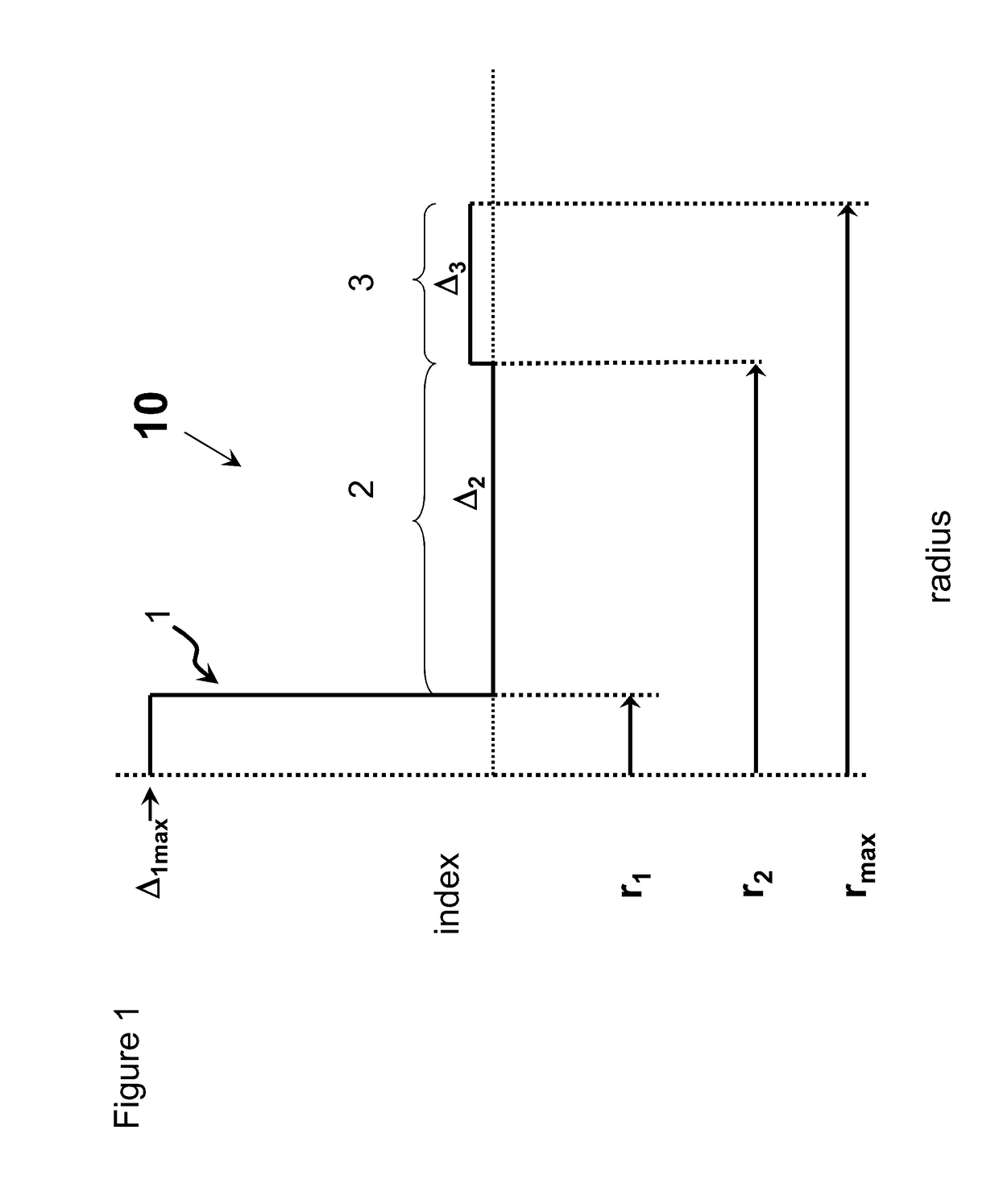
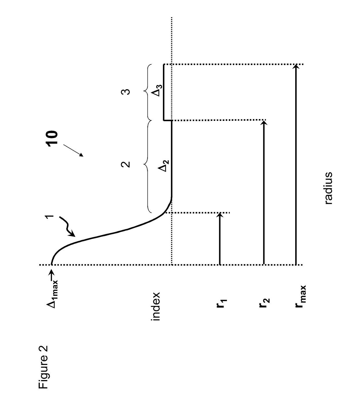
[0024]The “refractive index profile” is the relationship between refractive index or relative refractive index and the radial position within the waveguide fiber. The radius for each segment of the refractive index profile is given by the abbreviations r1, r2, r3, r4, etc. and lower and upper case are used interchangeably herein (e.g., r1 is equivalent to R1).
[0025]The term “relative refractive index percent” (also referred to herein as “relative refractive index”, and “refractive index delta”) is defined as Δ%=100 ×(ni2−nc2) / 2ni2, and as used herein nc is the average refractive index of undoped silica. As used herein, the relative refractive index is represented by Δ and its values are given in unit...
PUM
 Abstract
Description
Claims
Application Information