Broadband optical fiber

a broadband optical fiber and optical fiber technology, applied in the field of broadband optical fiber for telecommunications, can solve the problems of incompatible multimode fiber with higher bit rate components, inability to support a relatively low bit rate, undesirably low bandwidth of conventional 850 nm multimode fiber, etc., and achieve the effect of suitable performan

Inactive Publication Date: 2006-03-02
CORNING INC
View PDF21 Cites 41 Cited by
  • Summary
  • Abstract
  • Description
  • Claims
  • Application Information

AI Technical Summary

Benefits of technology

[0014] Preferably the optical fiber described and disclosed herein allows suitable performance at a plurality of operating wavelength windows between about 800 nm and about 1650 nm. More preferably, the optical fiber described and disclosed herein allows suitable single mode performance at a plurality of wavelengths from about 1260 nm to about 1650 nm and dual mode performance at a plurality of wavelengths from about 800 nm to about 1100 nm. In a preferred embodiment, the optical fiber described and disclosed herein is a triple window fiber which can accommodate operation in at least the 850 nm window, the 1310 nm window, and the 1550 nm window. In another preferred embodiment, the optical fiber described and disclosed herein is a multiple window fiber which can accommodate operation in at least the 850 nm window, the 980 nm window, the 1310 nm window, and the 1550 nm window.

Problems solved by technology

However, conventional 850 nm multimode fiber has undesirably low bandwidth and can support a relatively low bit rate.
Furthermore, conventional 850 nm multimode fiber is incompatible with higher bit rate components, such as 1300 nm single mode lasers and receivers.
Intermodal noise is a problem typically associated with multimode fibers.
Intermodal noise is related to a variation of the optical intensity at a given optical fiber output location due to optical interference between modes of different phase.
Many factors may act singly or in combination to produce phase changes that can cause intermodal noise.
Intermodal noise is a common problem in multimode fibers when used with highly coherent light sources, e.g., lasers, because the relative coherence of the modes allows the modes to affect the intensity of the light by interfering with each other.
Less coherent sources, such as LED's, have a short coherence length and therefore are only subject to intermodal noise in very short lengths of fiber.
However, LED sources are polychromatic and cause significant pulse broadening in the fiber, and pulse broadening reduces bandwidth.

Method used


Image

  • Broadband optical fiber
  • Broadband optical fiber
  • Broadband optical fiber

Examples


Embodiment Construction

[0026] Additional features and advantages of the invention will be set forth in the detailed description which follows and will be apparent to those skilled in the art from the description or recognized by practicing the invention as described in the following description together with the claims and appended drawings.

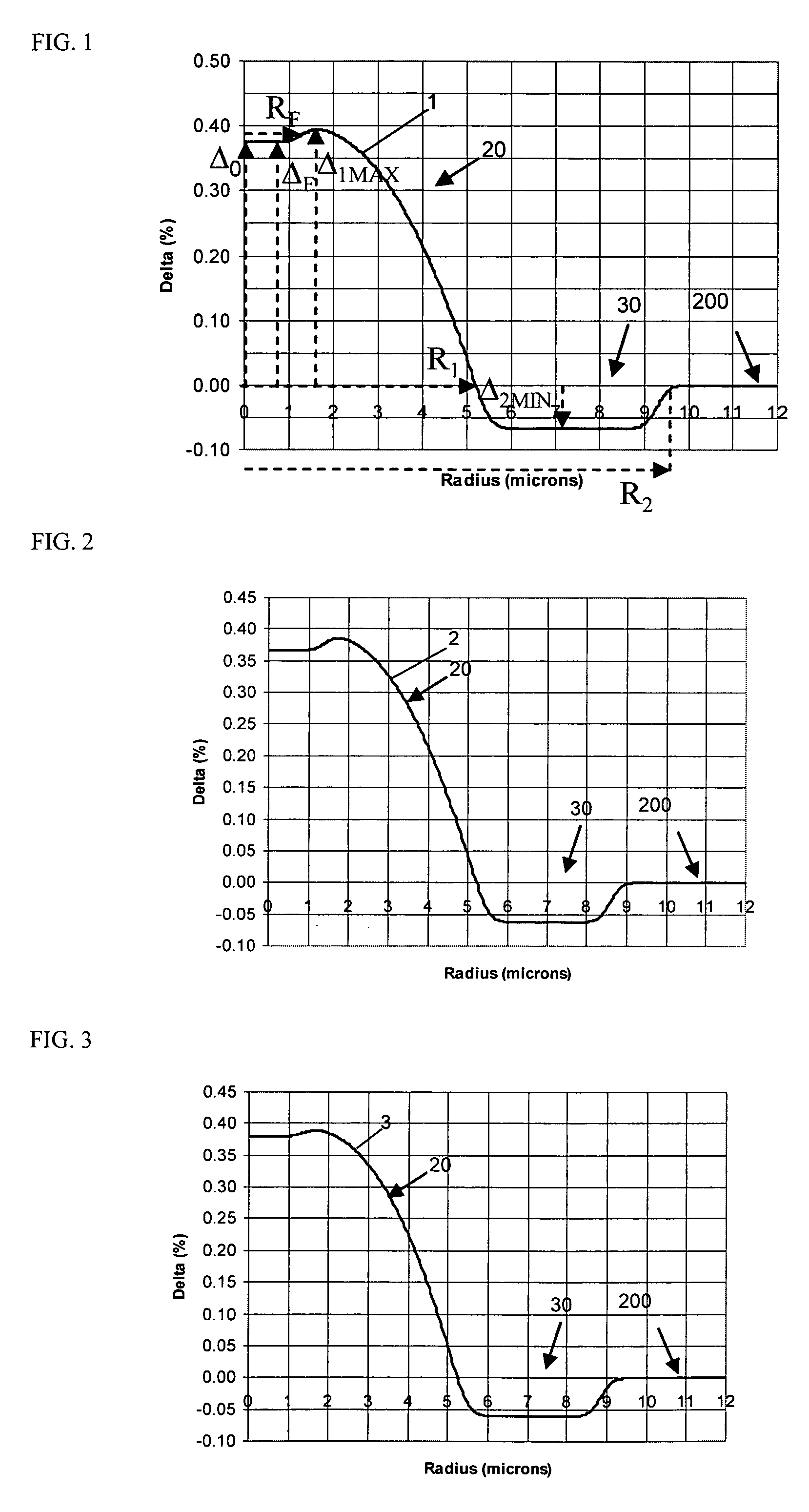
[0027] The “refractive index profile” is the relationship between refractive index or relative refractive index and waveguide fiber radius.

[0028] The “relative refractive index percent” is defined as Δ%=100×(ni2−nc2) / 2ni2, where ni is the maximum refractive index in region i, unless otherwise specified, and nc is the average refractive index of the cladding region. As used herein, the relative refractive index is represented by Δ and its values are given in units of “%”, unless otherwise specified. In cases where the refractive index of a region is less than the average refractive index of the cladding region, the relative index percent is negative and is referred to...


PUM


Abstract

An optical waveguide fiber having a multi-segmented core surrounded by a cladding, the core having a central segment and an annular segment surrounding the central segment. The central segment has a positive relative refractive index profile, and the annular segment has a negative relative refractive index profile. The broadband optical fiber has a bandwidth of at least 2 GHz-km for one or more wavelengths between 775 and 1100 nm.

Description

[0001] This application claims the benefit of priority under 35 U.S.C. § 119(e) of U.S. Provisional Application Ser. No. 60 / 605,744 filed on Aug. 31, 2004.BACKGROUND OF THE INVENTION [0002] 1. Field of the Invention [0003] The present invention is directed generally to optical fiber for telecommunications and more specifically to an optical fiber capable of multimode operation at wavelengths below about 1260 nm and single mode operation at wavelengths above about 1260 nm. [0004] 2. Technical Background [0005] Multimode fiber suitable for operation at 850 nm has been the preferred fiber for wiring homes and small businesses because the various system components (e.g. lasers, receivers) used in conjunction with this fiber are inexpensive. However, conventional 850 nm multimode fiber has undesirably low bandwidth and can support a relatively low bit rate. Furthermore, conventional 850 nm multimode fiber is incompatible with higher bit rate components, such as 1300 nm single mode lasers...

Claims


Application Information

Patent Timeline
Patent Type & Authority Applications(United States)
IPC IPC(8): G02B6/036
CPCG02B6/02014G02B6/02023G02B6/02047G02B6/02214H04B10/25137G02B6/0286G02B6/03611G02B6/03627G02B6/02266
Inventor BICKHAM, SCOTT R.
Owner CORNING INC
Why Eureka
Try Eureka