
Angle clamp with Z-axis attachment and quick acting buttons

a technology of z-axis and clamping device, which is applied in the direction of clamps, vices, manufacturing tools, etc., can solve the problems of time-consuming and inconvenient setup of this fixture, and another time-consuming process, and achieve the effect of easy removal

Inactive Publication Date: 2005-03-01
VALTRA
View PDF4 Cites 38 Cited by
  • Summary
  • Abstract
  • Description
  • Claims
  • Application Information

AI Technical Summary

Benefits of technology

A Z-axis attachment can be mounted by screws to the two side-plates accurately and securely. This Z-axis attachment comprises two side-plate extensions joined at one side at 90-degree relationship, a swing away clamping arm with quick release mechanism at the free end, a threaded shaft fed through the quick release mechanism and a clamping head pivoted to the inner end of the threaded shaft. The threaded shaft is positioned along the same direction as the one mounted on the bottom-plate when the clamping arm is at its clamping position. By turning this threaded shaft inward, a third workpiece can be clamped against the corner of the two side-plate extensions of the Z-axis attachment at a position perpendicular to the bottom-plate. As a result, three workpieces can be clamped in three dimensional relationship along three mutually perpendicular directions (X, Y and Z axes) with the setup of one clamping device. In welding applications, the Z-axis attachment is also needed to hold the third welded part securely in place, and to counteract the contraction force induced by a cooling weld.
The assembled workpiece, which may be very bulky, can be removed easily with the clamping arm of the Z-axis attachment swung away to one side of the angle clamp.

Problems solved by technology

However, the setup of this fixture is time-consuming and sometimes inconvenient.
This is another time-consuming process.

Method used


Image

  • Angle clamp with Z-axis attachment and quick acting buttons
  • Angle clamp with Z-axis attachment and quick acting buttons
  • Angle clamp with Z-axis attachment and quick acting buttons

Examples


Embodiment Construction

With the help of the drawings and the detail description below, the features of the present invention will be apparent and fully understandable.

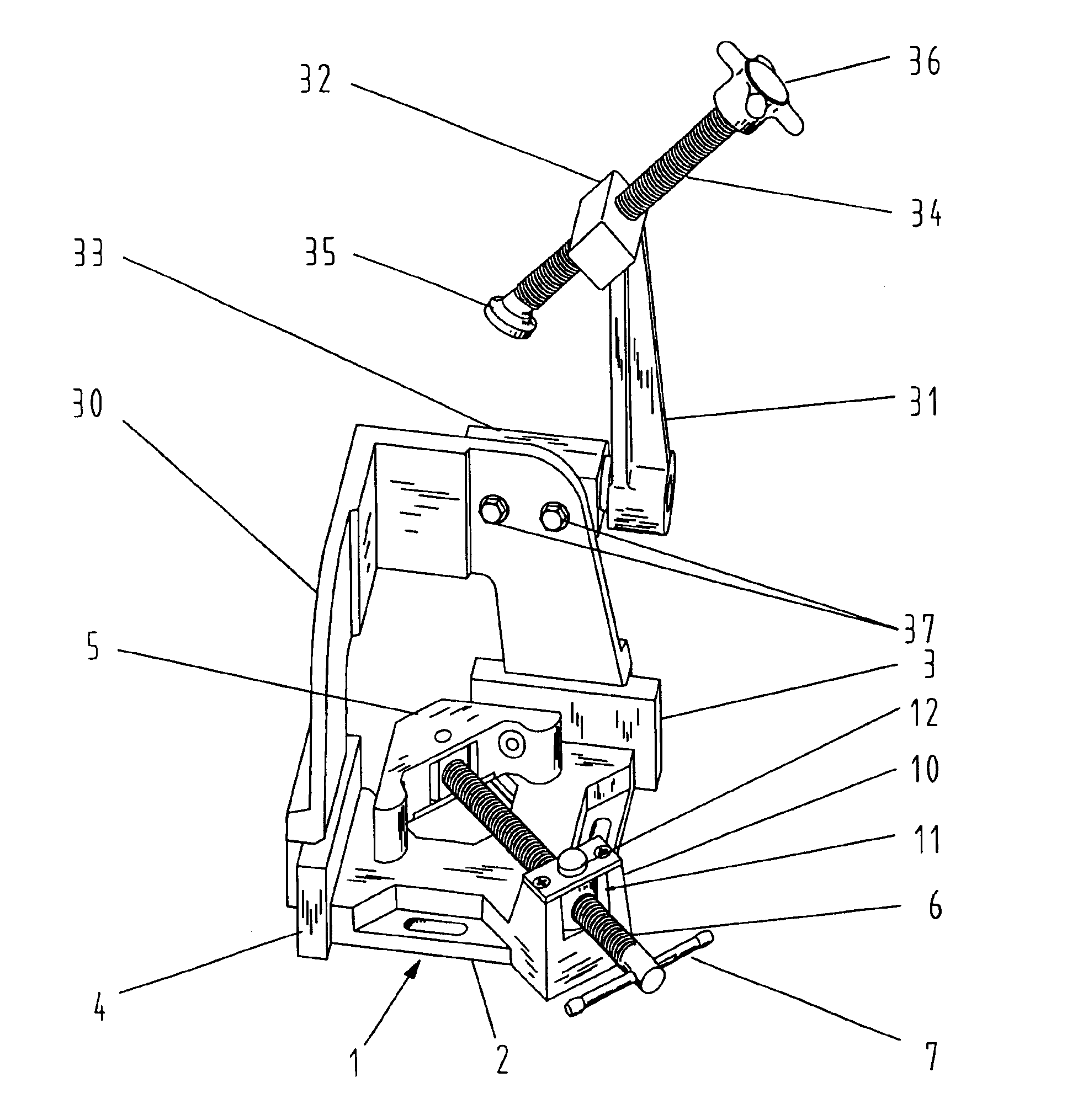
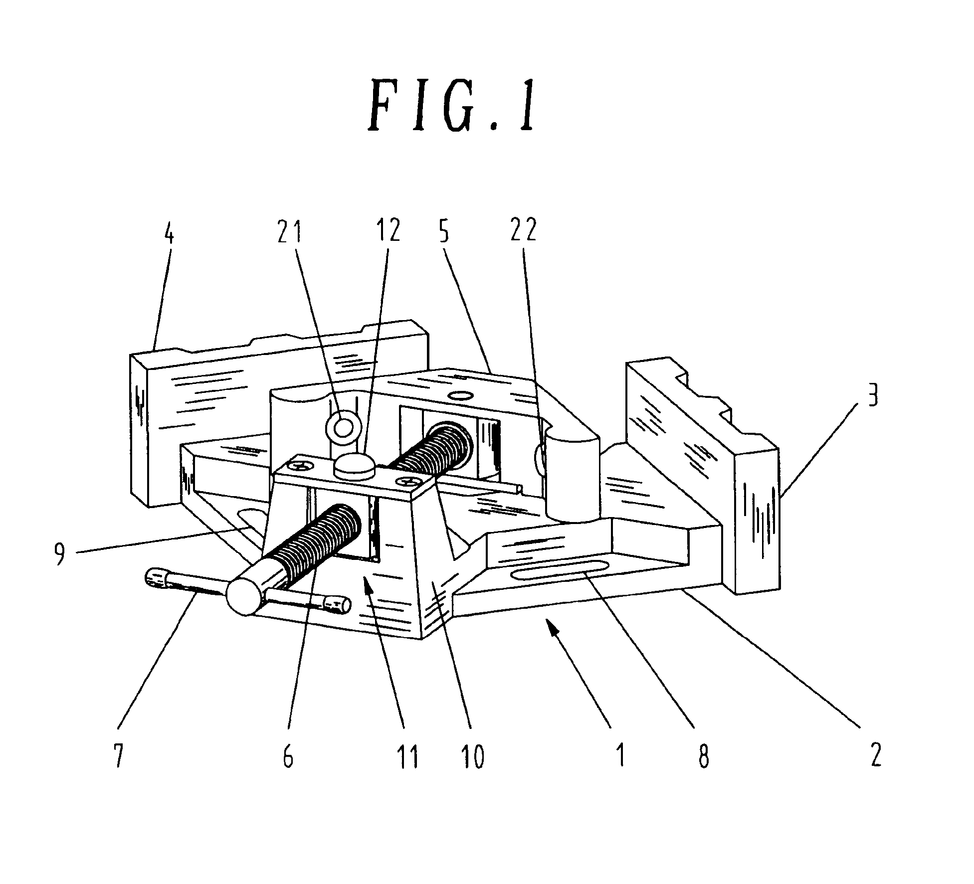
Referring to FIG. 1, the angle clamp 1 comprises three mutually perpendicular base plates, a square shape bottom-plate 2, two rectangular side-plates 3 and 4, and a floating right-angle head 5 attached to a threaded shaft 6 with handle 7. The two side-plates 3 and 4 are located at two adjacent edges of the square shape bottom-plate 2 so that both are perpendicular to the bottom-plate 2 and at right angle to each other. Two slotted holes 8 and 9 are provided along the other two adjacent edges of bottom-plate 2 for accepting screws to fix the angle clamp 1 to a work desk. At the vertex of these two adjacent edges, a vertical ear 10 is equipped at 135 degrees to these edges for feeding the threaded shaft 6. Threaded shaft 6 is fed through a quick release mechanism 11 pivoted at the upper center of ear 10 in a normal direction at 45 degrees to t...


PUM


Abstract

A clamping device allows welding, or other application of three-axis workpieces by providing X, Y, and Z clamping surfaces. The device is equipped with three mutually perpendicular base plates and on one of which a floating right-angle head is mounted through a threaded shaft with quick acting button for rapid advance and return. Inserts like leveling pads can be inserted to the tooling holes in the floating right-angle head to increase working access, especially at the joint area where the X and Y axes meet. A Z-axis attachment including base plate extension with clamping arm and a threaded shaft is mounted by screws to two of the base plates. The clamping arm of the Z-axis can be swung away for easy removal of the workpiece after work. The outside walls of the base plates are machined flat and square so that the angle clamp can be laid sideway to hold a workpiece vertically in place.

Description

BACKGROUND OF THE INVENTION1. Field of the InventionThe present invention relates to an improved clamping device which can be used to hold workpieces in a three dimensional 90-degree relationship with the addition of the Z-axis attachment. And the workpieces can easily be removed after work by pressing the quick acting buttons to release the threaded shafts mounted with the clamping heads. The swing away clamping arm of the Z-axis attachment gives even more room for easier removal of the workpieces if necessary.2. Description of the Related ArtA typical clamp (or vise) generally includes a fixed head (or jaw) and a movable head (or movable jaw) attached to one end of a threaded shaft. Clamping action is achieved by turning the threaded shaft so that the movable head is moved towards the fixed head against the workpiece. By turning the threaded shaft counterclockwise, the movable head is moved away from the fixed head and hence the workpiece is released. With such a device, a workpie...

Claims


Application Information

Patent Timeline
IPC IPC(8): B25B5/00B25B5/10B25B5/14
CPCB25B5/003B25B5/142B25B5/10
Inventor WONG, HARRY
Owner VALTRA
Features
  • Generate Ideas
  • Intellectual Property
  • Life Sciences
  • Materials
  • Tech Scout
  • Unparalleled Data Quality
  • Higher Quality Content
  • 60% Fewer Hallucinations
Learn More