Connector

Inactive Publication Date: 2005-03-01
YAZAKI CORP +1
View PDF6 Cites 28 Cited by
  • Summary
  • Abstract
  • Description
  • Claims
  • Application Information

AI Technical Summary

Benefits of technology

It is a first object of the present invention to make a fixing strength between a central contact and an insulating housing higher than that in the prior art in a connector comprising the central contact, the insulating housing, the insulating housing having a contact inserting hole for press-fit therein of the central contact, and an external contact adapted to engage with the insulating housing by insertion therein of the insulating housing with the central contact press-fitted therein, the insulating housing being formed in a generally cylindrical shape. An engaging hole is formed in a side wall of the central contact, while a retaining beam is formed on a side wall of the insulating housing, with a retaining pawl being formed in part of the retaining beam. When the insulating housing with the central contact press-fitted therein is inserted into the external contact, the retaining beam is pushed by the external contact and moves toward the contact inserting hole and the retaining pawl comes into engagement with the engaging hole, whereby the central contact and the insulating housing are fixed together. Thus, the central contact and the insulating housing are fixed together by both press-fit engagement of the central contact with the contact inserting hole and engagement of the engaging pawl with the engaging hole. Consequently, the fixing strength between the central contact and the insulating housing can be enhanced in comparison with the prior art in which both are fixed together by press-fitting of the central contact into the contact inserting hole.
It is a second object of the present invention to enhance the fixing strength between the central contact and the insulating housing in a well-balanced state without making the structure of the central contact and that of the insulating housing so complicated. A pair of engaging holes are formed in opposed side wall portions of the central contact, a pair of retaining beams are formed in opposed side wall portions of the insulating housing, and retaining pawls are projected respectively from front ends of the retaining beams. When the insulating housing with the central contact press-fitted therein is inserted into the external contact, the pair of retaining beams are pushed by the external contact and move toward the contact inserting hole, while the pair of engaging pawls are engaged with the corresponding p

Problems solved by technology

Thus, there has been the problem that the fixing strength between the plug pin 100 and the insulating housing 102 is not sufficient and that therefore the plug pin 100 is apt to come off from the insulating housing 102.
Particularly, in a standard type connector to which a relatively thick coaxial cable is connected, a base end-side outer periphery portion of

Method used


Image

  • Connector
  • Connector
  • Connector

Examples


Embodiment Construction

An embodiment of the present invention will be described hereinunder with reference to the accompanying drawings.

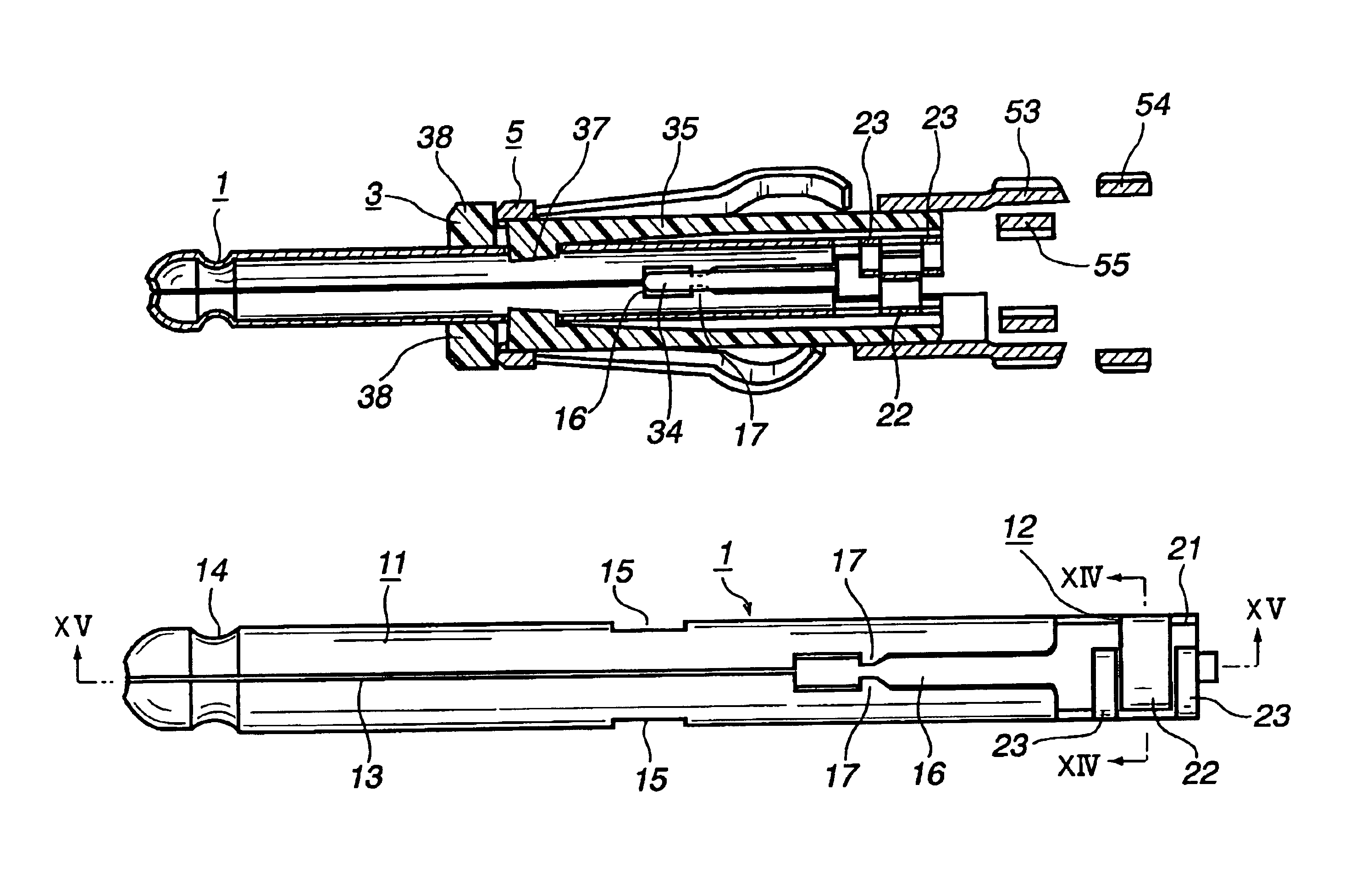
FIGS. 4 to 9 illustrate an entire construction of a connector (e.g., an automobile antenna plug) embodying the present invention. In these figures, the numeral 1 denotes a plug pin as an example of a central contact, numeral 3 denotes an insulating housing, and numeral 5 denotes an external contact.

The plug pin 1 is formed by punching and bending a conductive metallic sheet. As shown in FIGS. 10 to 15, the plug pin 1 is composed of a generally cylindrical pin body 11 and a connecting portion 12 which is integrally contiguous to a base end side (right side in FIG. 4) of the pin body 11.

An upper portion of the pin body 11 is separated by a slit 13 formed in parallel with an axial direction of the pin body. A front end side (left side in FIG. 10) of the pin body 11 is formed in a generally semispherical shape and a base end-side outer periphery portion 14 of the semispherica...


PUM


Abstract

A pair of engaging holes 15 are formed in side wall portions of the plug pin 1 and a pair of engaging beams 35 are formed on side wall portions of an insulating housing 3, the engaging beams 35 being pushed by an external contact 5 and moving toward a pin inserting hole 31 when the insulating housing 3 with the plug pin 1 press-fitted therein is inserted into the external contact 5. As a result, a pair of retaining pawls 37 are put in engagement with the engaging holes 15, whereby the plug pin 1 and the insulating housing 3 are fixed to each other. Since the plug pin 1 and the insulating housing 3 are fixed together by both press-fit engagement of the plug pin 1 into the insulating housing 3 and engagement of the retaining pawls 37 with the engaging holes 15, the strength of the fixing is enhanced.

Description

BACKGROUND OF THE INVENTIONThe present invention relates to a connector comprising a central contact, an insulating housing having a contact inserting hole into which the central contact is press-fitted, and an external contact adapted to engage with the insulating housing by insertion therein of the insulating housing with the central contract press-fitted therein. For example, the present invention is concerned with an automobile antenna plug connected to an end portion of a coaxial cable.Heretofore, as this type of a connector there has been known such a coaxial connector as shown in FIGS. 1A to 1C and FIGS. 2 and 3, which connector is disclosed, for example, in Japanese Patent No. 3059432 issued Jul. 4, 2000.More particularly, such a plug pin 100 as shown in FIG. 1A, which serves as a central contact, is press-fitted into a cylindrical hollow portion 104 from behind an insulating housing 102, as shown in FIG. 1B. At this time, a pair of retaining projections 106 and a pair of re...

Claims


Application Information

Patent Timeline
IPC IPC(8): H01R13/00H01R13/646H01R4/18H01R13/41H01R13/40H01R9/05H01R4/10
CPCH01R24/40H01R4/185H01R9/0518H01R2201/02H01R2103/00H01R13/41
Inventor ENDO, TAKAYOSHIABE, KIMIHIROKAMEYAMA, ISAOYOSHIURA, YASUO
Owner YAZAKI CORP
Why Eureka
Try Eureka