Wire crimping structure and shielded conductive path

a conductive path and wire crimping technology, applied in the direction of insulated conductors, cables, coupling device connections, etc., can solve the problems of weak fixing force between the crimping portion and the wire, and no possibility that the restricting portion will unlock, so as to improve the fixing strength and improve the fixing strength. the effect of the first and second crimping pieces

Active Publication Date: 2021-09-28
AUTONETWORKS TECH LTD +2
View PDF28 Cites 0 Cited by
  • Summary
  • Abstract
  • Description
  • Claims
  • Application Information

AI Technical Summary

Benefits of technology

[0007]The first and second locking portions lock the restricting portion in the directions opposite to each other along the circumferential direction of the wire to restrict displacements of the first and second crimping pieces in a diameter expanding direction. The first and second locking portions are not locked directly to each other, but individually lock the restricting portion. Thus, a formation range of the first locking portion in the axial direction of the wire can be expanded to the entire area of the first crimping piece and a formation range of the second locking portion in the axial direction of the wire can be expanded to the entire area of the second crimping piece. By doing so, a locking margin between the first locking portion and the restricting portion and a locking margin between the restricting portion and the second locking portion can be enlarged and fixing strength between the wire and the crimping portion can be enhanced. Note that the circumferential direction of the invention includes both a clockwise direction and a counterclockwise direction when viewed parallel to an axis of the wire.
[0009]The first locking portion and the second locking portion may be disposed side by side in an axial direction of the wire and may lock the restricting portion to sandwich the restricting portion in the circumferential direction. According to this configuration, an extending length of one crimping piece in the circumferential direction becomes longer as compared to the case where the first and second locking portions are disposed at the same position in the axial direction of the wire and lock the restricting portion to pull the restricting portion in the circumferential direction. Thus, fixing strength by the first and second crimping pieces is improved.
[0010]The first crimping piece may include a first base and a first extending portion. The first base may be connected to the base plate and may extend in the circumferential direction from the base plate. The first extending portion may extend in the circumferential direction from an extending end of the first base and may be narrower than the first base. The second crimping piece may include a second base and a second extending portion. The second base may be connected to the base plate and may extend in the circumferential direction from the base plate. The second extending portion may extend in the circumferential direction from an extending end of the second base and may be narrower than the second base. The first and second extending portions may be disposed side by side in the axial direction of the wire. According to this configuration, extending lengths of the first and second crimping pieces in the circumferential direction become longer even without expanding the formation range of the first and second crimping pieces in the axial direction of the wire. Thus, fixing strength is improved.

Problems solved by technology

Thus, there is a problem that a fixing force between the crimping portion and the wire is weak.
However, there is no possibility that the restricting portion will unlock from the first locking portion or the second locking portion.

Method used


Image

  • Wire crimping structure and shielded conductive path
  • Wire crimping structure and shielded conductive path
  • Wire crimping structure and shielded conductive path

Examples


first embodiment

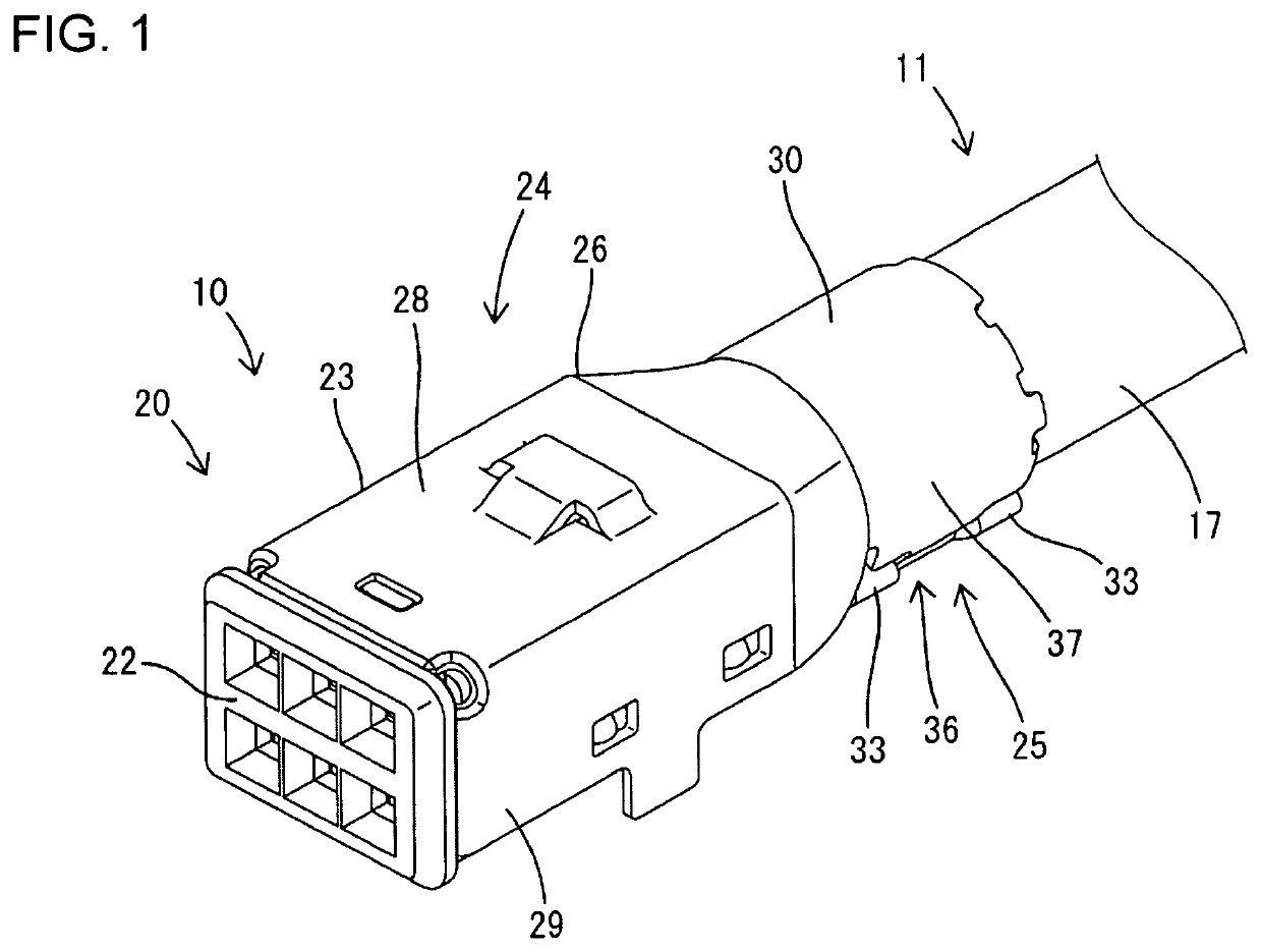
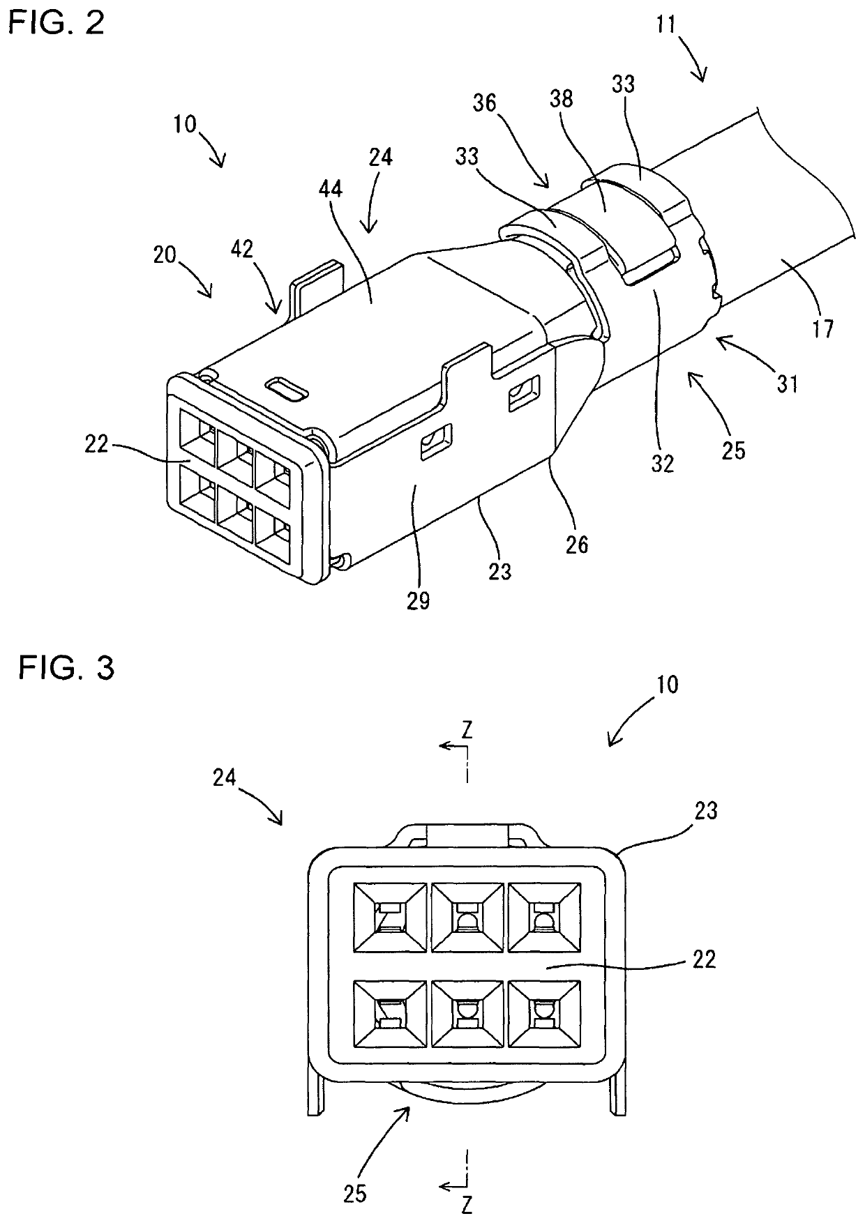
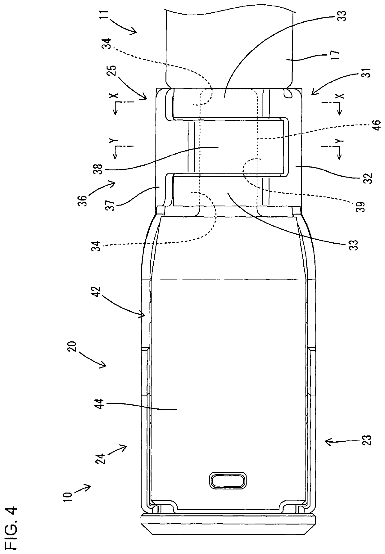
[0031]A first embodiment of the invention is described with reference to FIGS. 1 to 12. Note that, in the following description, an oblique right-lower side in FIGS. 1, 2, 8 and 11 and a left side in FIGS. 4, 7 and 9 are defined as a front side concerning a front-rear direction. Upper and lower sides shown in FIGS. 1 to 3, 5 to 8, 10 and 11 are defined as upper and lower sides concerning a vertical direction. An oblique left-upper side in FIGS. 1, 8 and 11 is defined as a right side and left and right sides shown in FIGS. 5, 6 and 10 are directly defined as left and right sides concerning a lateral direction. Note that a circumferential direction in the first embodiment includes both a clockwise direction and a counterclockwise direction when viewed in parallel to an axis of a shielded wire 11.

[0032]A wire crimping structure of the first embodiment is applied to a shielded conductive path 10. The shielded conductive path 10 is formed such that a shield terminal 20 is fixed to a fron...

second embodiment

[0072]Next, a second embodiment of the invention is described with reference to FIGS. 13 and 14. A shielded conductive path 50 to which a crimping structure of the second embodiment is applied differs from that of the first embodiment in the configurations of first and second crimping pieces 51, 55. Since the other components are the same as in the first embodiment, the same components are denoted by the same reference signs and structures, functions and effects thereof are not described.

[0073]As in the first embodiment, the first crimping piece 51 of the second embodiment is formed such that front and rear first extending portions 53 narrower than a first base 52 are formed on the extending end of the first base portion 52 and first locking portions 54 are formed on extending end parts of the respective first extending portions 53. The first locking portion 54 is formed by cutting and raising a part of the first extending portion 53 toward an inner peripheral side (in a direction a...

third embodiment

[0074]Next, a third embodiment of the invention is described with reference to FIGS. 15 and 16. A shielded conductive path 60 to which a crimping structure of the third embodiment is applied differs from that of the first embodiment in the configurations of first and second crimping pieces 61, 65. Since the other components are the same as in the first embodiment, the same components are denoted by the same reference signs and structures, functions and effects thereof are not described.

[0075]As in the first embodiment, the first crimping piece 61 of the third embodiment is formed such that front and rear first extending portions 63 narrower than a first base 62 are formed on the extending end of the first base 62, and first locking portions 64 are formed on extending end parts of the respective first extending portions 63. The first locking portion 64 is formed by cutting and raising a part of the first extending portion 63 toward an inner peripheral side (in a direction approaching...


PUM


Abstract

A crimping portion (25) of a connection structure of a shielded wire (11) includes a base plate (30) along an outer periphery of the shielded wire (11). A first crimping piece (31) is cantilevered from a first side of the base plate (30) and is crimped to surround the shielded wire (11). A second crimping piece (36) is cantilevered in a direction opposite the first crimping piece (31) from a second side of the base plate (30) and is crimped to surround the shielded wire (11). A restricting portion (46) is disposed along the outer periphery of the shielded wire (11). First locking portions (34) of the first crimping piece (31) and second locking portions (39) of the second crimping piece (36) lock the restricting portion (46) in directions opposite to each other along the circumferential direction.

Description

BACKGROUNDField of the Invention[0001]The invention relates to a wire crimping structure and a shielded conductive path.Related Art[0002]Japanese Unexamined Patent Publication No. 2011-023245 discloses a structure for connecting a crimping portion of a connecting member to a wire. Two crimping pieces of the crimping portion are formed with hooks. The hooks directly lock to each other as the crimping pieces are crimped to be wound on the outer periphery of the wire. This direct locking of the hooks restricts displacement of the crimping pieces in a diameter expanding direction and ensures a fixing strength between the crimping portion and the wire.[0003]Each hook is a combination of a part of the crimping piece cut in an axial direction of the wire (i.e. width direction of the crimping piece) and a part of the crimping piece projecting in the axial direction of the wire. Thus, a locking margin of each hook in the axial direction of the wire has to be smaller than widths of the crimpi...

Claims


Application Information

Patent Timeline
Patent Type & Authority Patents(United States)
IPC IPC(8): H01R9/03H01R4/18H01R13/6581
CPCH01R4/18H01R13/6581H01B7/18H01R13/6593H01R4/184H01R13/5808
Inventor HAMADA, KAZUAKIMURATA, ATSUSHI
Owner AUTONETWORKS TECH LTD
Why Eureka
Try Eureka