
Optical filter device and electronic apparatus

a filter device and filter technology, applied in the field of optical filter devices and electronic devices, can solve the problems of warping of the interference filter itself, the degradation of optical properties, and the warping of the reflection film, so as to prevent the change of the optical properties of the interference filter, prevent the warping of the fixed reflection film, and improve the air tightness of the inner space

Active Publication Date: 2016-05-24
SEIKO EPSON CORP
View PDF14 Cites 0 Cited by
  • Summary
  • Abstract
  • Description
  • Claims
  • Application Information

AI Technical Summary

Benefits of technology

This configuration stabilizes optical properties and ensures sufficient impact resistance by managing thermal stress and mechanical loads effectively.

Problems solved by technology

JP-A-2008-70163 and JP-T-2005-510756 disclose description of accommodation and fixation of the interference filter in the inner portion of the housing, however, do not disclose a specific method.
In addition, in a case of fixing the interference filter with an adhesive, there was a concern that the reflection film is warped due to an effect from contraction at the time when an adhesive is hardened, and there was a problem of degradation of optical properties.
In detail, in a case where the fixing member is disposed over the entire surface between the second substrate and the base substrate, since there is no way to avoid expansion and contraction stress due to the difference in both coefficients of thermal expansion of the second substrate and the base substrate, the warping of the interference filter itself occurs.
In addition, in a case where an adhesive is used as the fixing member, stress due to contraction at the time of hardening is operated over the entire second substrate, and thus the warping occurs.
When the movement thereof is rapid, there is a concern that fixing (bonding) strength of the fixing member is exceeded and peeling-off or cracks on the fixing member occur, however, according to the configuration of the application example, at the time of the impact, first, the spacer portions come in contact with the base substrate to function as stoppers.

Method used


Image

  • Optical filter device and electronic apparatus
  • Optical filter device and electronic apparatus
  • Optical filter device and electronic apparatus

Examples


embodiment 1

[0041]Hereinafter, an optical filter device according to Embodiment 1 will be described with reference to the drawings.

1. Outline of Optical Filter Device

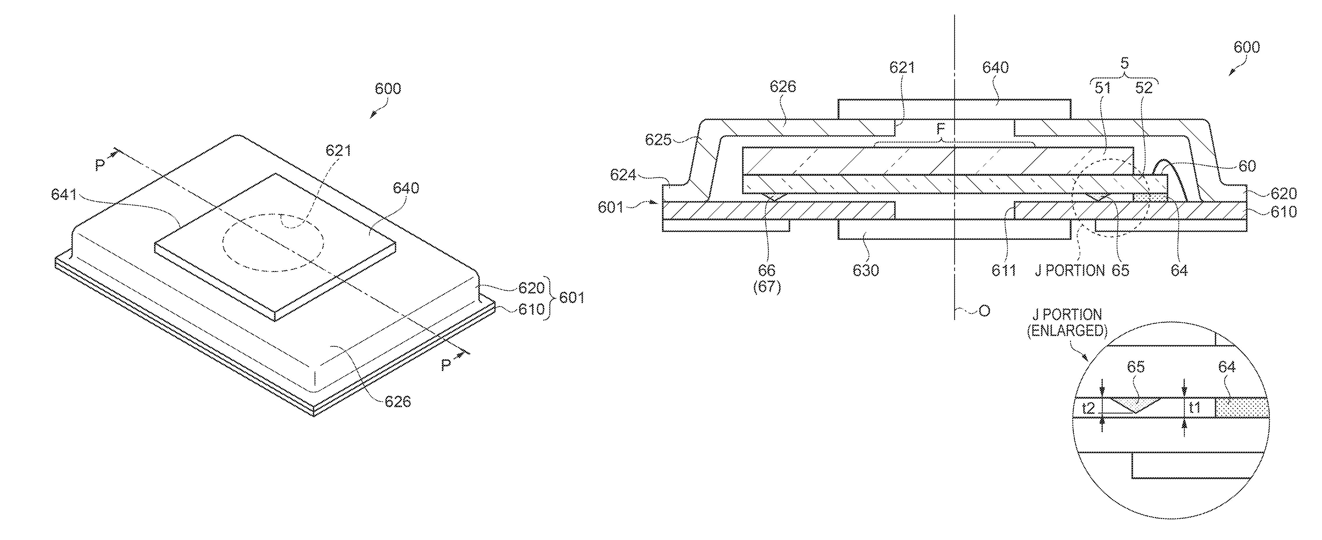
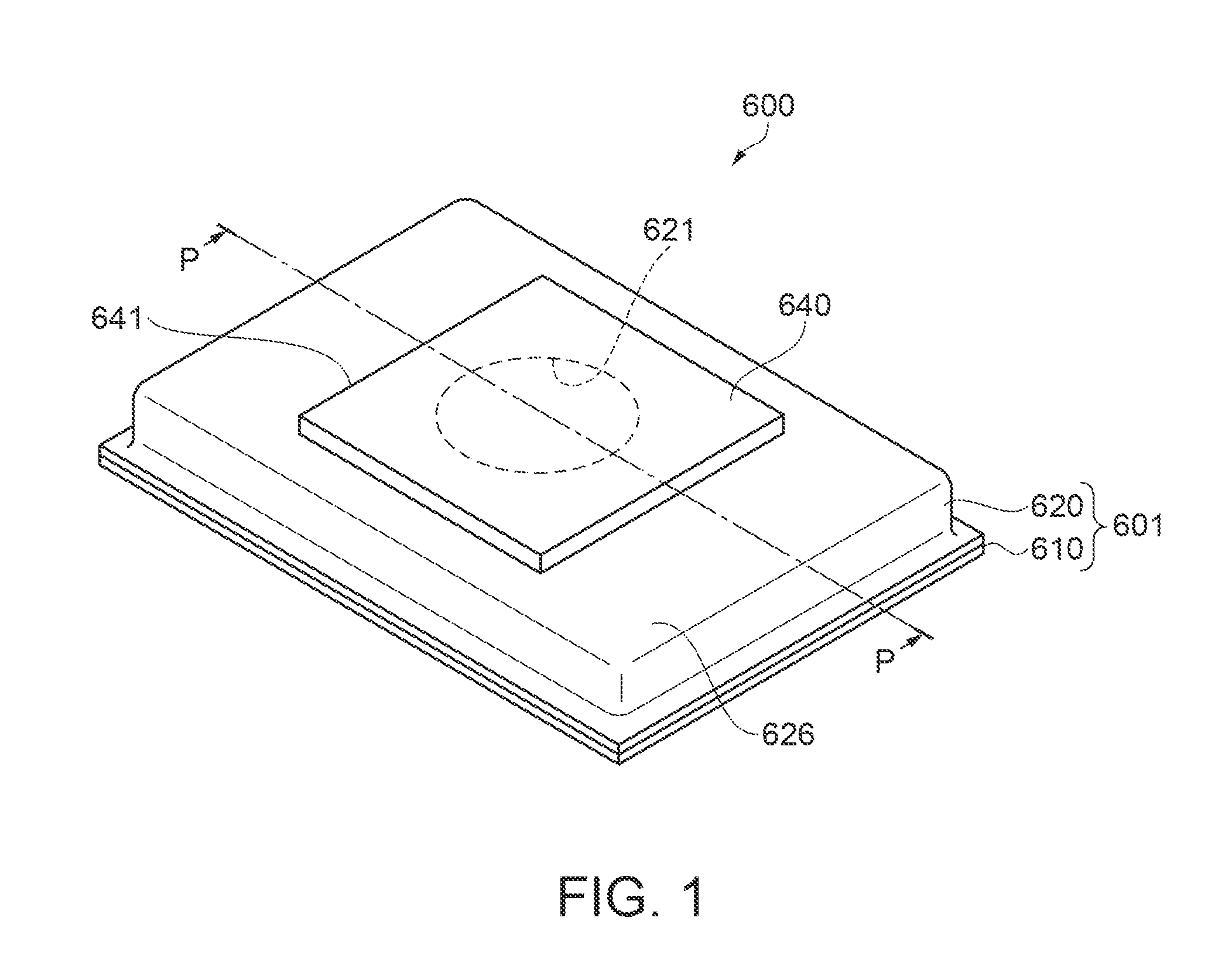
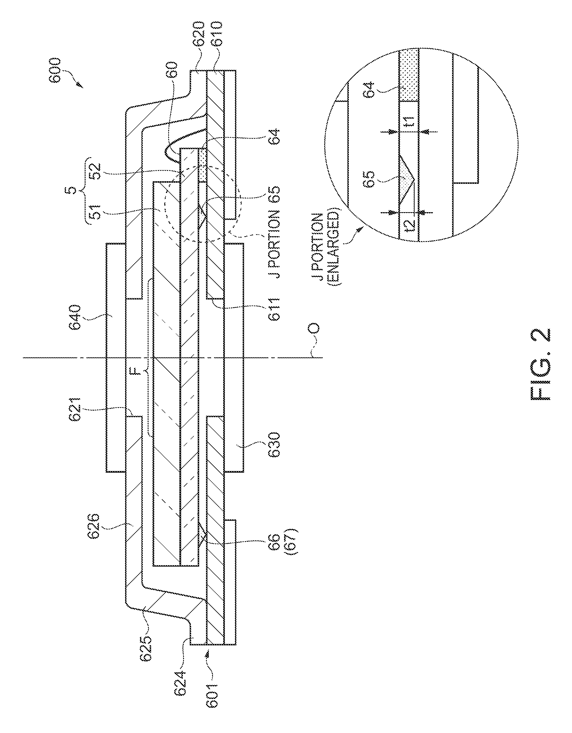
[0042]FIG. 1 is a perspective view of a schematic configuration of the optical filter device according to Embodiment 1. FIG. 2 is a side cross-sectional view of a cross section taken along line P-P of FIG. 1.

[0043]An optical filter device 600 is an optical filter using an interference operation of light, and is a optical device which extracts and emits light having a predetermined target wavelength, from incident investigation target light. The optical filter device 600 is configured with a housing 601, an interference filter 5 (see FIG. 2) which is accommodated in the housing, and the like.

[0044]Such an optical filter device 600 is embedded in an optical module such as a colorimetric sensor, or an electronic apparatus such as a colorimetry apparatus or a gas analysis apparatus, for example. A configuration of an optical module or ...

embodiment 2

[0116]Hereinafter, an optical filter device according to Embodiment 2 will be described with reference to the drawings.

Outline of Optical Filter Device

[0117]FIG. 5 is a side cross-sectional view of the optical filter device according to Embodiment 2 and corresponds to FIG. 2. Herein, an outline of an optical filter device 605 according to the embodiment will be described mainly with reference to FIG. 5 and suitably with FIG. 3. In the description, the same configuration components as Embodiment 1 described above are denoted with the same reference numerals and the overlapped descriptions are omitted.

[0118]The optical filter device 605 of the embodiment is different from Embodiment 1 in which the spacer portion is formed also on the surface side of the interference filter 5. The other configurations are the same as the optical filter device 600 of Embodiment 1.

[0119]As shown in FIG. 5, in the interference filter 5 of the embodiment, spacer portions 75 and 76 (77) are formed also on t...

embodiment

Operating Effect of Embodiment

[0147]The colorimetry apparatus 1 of the embodiment includes the optical filter device 600 of the embodiment. As described above, according to the optical filter device 600, although the movable substrate 52 and the base substrate 610 are fixed to each other using the fixing member 64 which is disposed on one portion, the stress or the like due to a difference in coefficients of thermal expansion is hardly operated to the movable substrate 52 or the fixed substrate 51. Accordingly, it is possible to suppress warping of the fixed reflection film 54 of the fixed substrate 51 or the movable reflection film 55 of the movable substrate 52. Therefore, it is possible to prevent the change of the optical properties of the interference filter 5 which occurs due to the warping of the reflection films 54 and 55. In addition, since the optical filter device 600 has high airtightness of the inner space and has no invasion of a foreign material such as a water partic...


PUM


Abstract

An interference filter is fixed with respect to a base substrate by a fixing member which is disposed on one portion which is on the outer side of a filter region. Accordingly, since the periphery end of the interference filter, other than a portion (end portion) in which the fixing member is disposed, becomes a floated state (free end), it is possible to suppress the warping of the interference filter even when there is the difference in coefficients of thermal expansion with the base substrate. Further, spacer portions which are lower than the height of the fixing member are formed outside the filter region and on the portion separated from the fixing member. At the time of the impact, since the spacer portions come in contact with the base substrate to function as stoppers, it is possible to suppress occurrence of peeling-off or cracks on the fixing member.

Description

BACKGROUND[0001]1. Technical Field[0002]The present invention relates to an optical filter device, and an electronic apparatus including the optical filter device.[0003]2. Related Art[0004]In the related art, an interference filter has been known in which reflection films which are provided to oppose each other with a predetermined gap in between, on surfaces of a pair of substrates which oppose each other. In addition, an optical filter device has been known in which such an interference filter is accommodated in a housing (for example, see JP-A-2008-70163 and JP-T-2005-510756).[0005]An infrared type gas detector (optical filter device) disclosed in JP-A-2008-70163 includes a package (housing) which has a plate-shaped table (base substrate) and a cylindrical cap. In the housing, a periphery portion of the base substrate and a cylindrical end portion of the cap are welded or bonded to be connected to each other, and a space for accommodating a Fabry-Perot filter (interference filter...

Claims


Application Information

Patent Timeline
Patent Type & Authority Patents(United States)
IPC IPC(8): G02B5/28G02B7/00G02B5/00
CPCG02B5/284G02B5/00G02B5/28G02B7/006
Inventor KOIKE, SHIGEMITSU
Owner SEIKO EPSON CORP
Learn More