Wire crimping structure and shielded conductive path
a conductive path and wire crimping technology, applied in the direction of insulated conductors, cables, coupling device connections, etc., can solve the problems of weak fixing force between the crimping portion and the wire, and no possibility that the restricting portion will unlock, so as to improve the fixing strength and improve the fixing strength. the effect of the first and second crimping pieces
- Summary
- Abstract
- Description
- Claims
- Application Information
AI Technical Summary
Benefits of technology
Problems solved by technology
Method used
Image
Examples
first embodiment
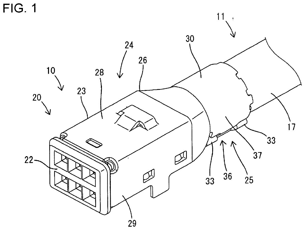
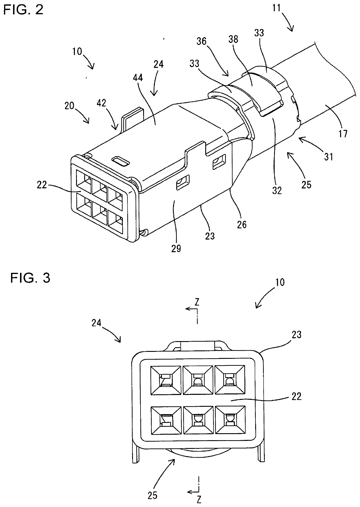
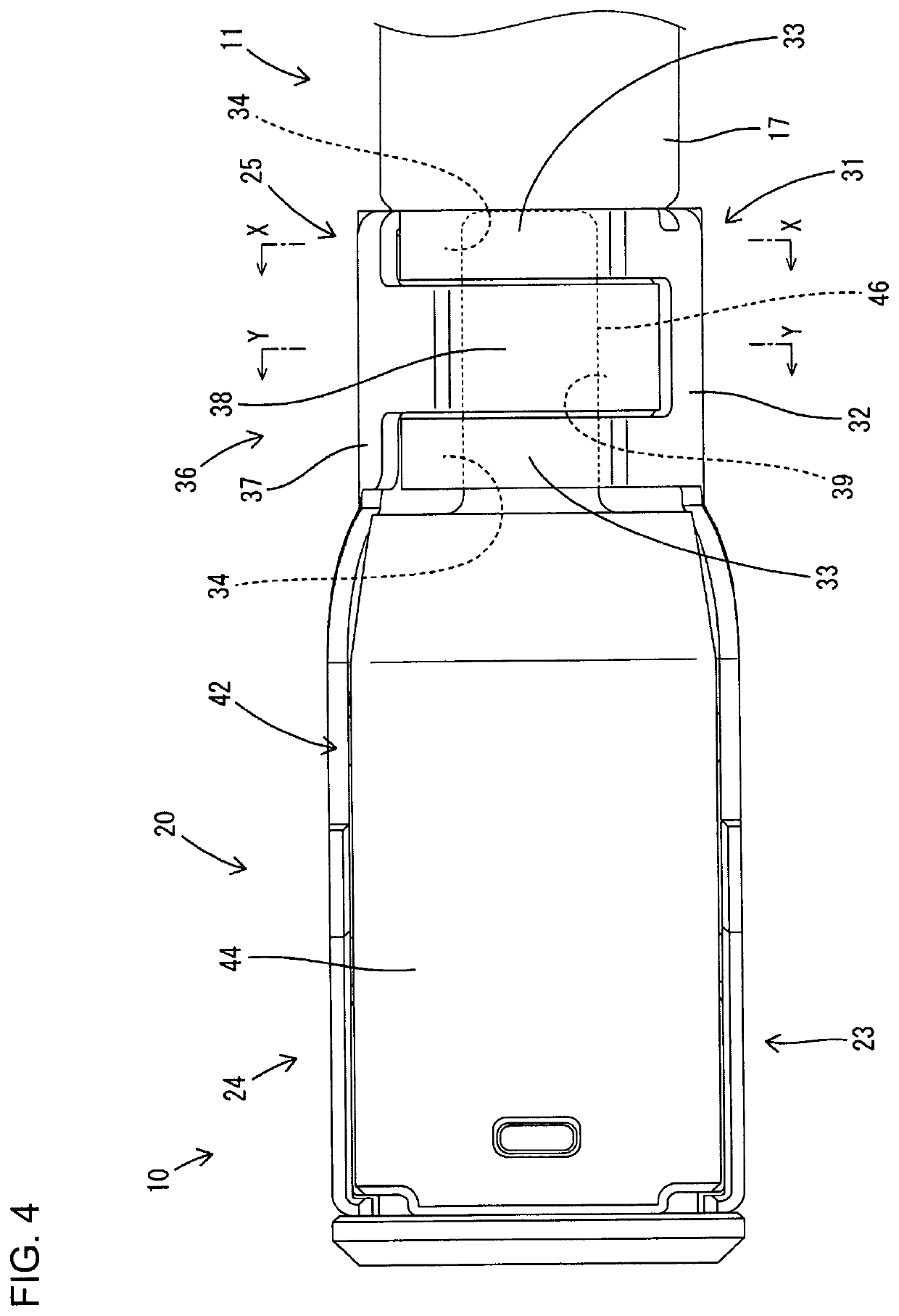
[0031]A first embodiment of the invention is described with reference to FIGS. 1 to 12. Note that, in the following description, an oblique right-lower side in FIGS. 1, 2, 8 and 11 and a left side in FIGS. 4, 7 and 9 are defined as a front side concerning a front-rear direction. Upper and lower sides shown in FIGS. 1 to 3, 5 to 8, 10 and 11 are defined as upper and lower sides concerning a vertical direction. An oblique left-upper side in FIGS. 1, 8 and 11 is defined as a right side and left and right sides shown in FIGS. 5, 6 and 10 are directly defined as left and right sides concerning a lateral direction. Note that a circumferential direction in the first embodiment includes both a clockwise direction and a counterclockwise direction when viewed in parallel to an axis of a shielded wire 11.
[0032]A wire crimping structure of the first embodiment is applied to a shielded conductive path 10. The shielded conductive path 10 is formed such that a shield terminal 20 is fixed to a fron...
second embodiment
[0072]Next, a second embodiment of the invention is described with reference to FIGS. 13 and 14. A shielded conductive path 50 to which a crimping structure of the second embodiment is applied differs from that of the first embodiment in the configurations of first and second crimping pieces 51, 55. Since the other components are the same as in the first embodiment, the same components are denoted by the same reference signs and structures, functions and effects thereof are not described.
[0073]As in the first embodiment, the first crimping piece 51 of the second embodiment is formed such that front and rear first extending portions 53 narrower than a first base 52 are formed on the extending end of the first base portion 52 and first locking portions 54 are formed on extending end parts of the respective first extending portions 53. The first locking portion 54 is formed by cutting and raising a part of the first extending portion 53 toward an inner peripheral side (in a direction a...
third embodiment
[0074]Next, a third embodiment of the invention is described with reference to FIGS. 15 and 16. A shielded conductive path 60 to which a crimping structure of the third embodiment is applied differs from that of the first embodiment in the configurations of first and second crimping pieces 61, 65. Since the other components are the same as in the first embodiment, the same components are denoted by the same reference signs and structures, functions and effects thereof are not described.
[0075]As in the first embodiment, the first crimping piece 61 of the third embodiment is formed such that front and rear first extending portions 63 narrower than a first base 62 are formed on the extending end of the first base 62, and first locking portions 64 are formed on extending end parts of the respective first extending portions 63. The first locking portion 64 is formed by cutting and raising a part of the first extending portion 63 toward an inner peripheral side (in a direction approaching...
PUM
 Abstract
Description
Claims
Application Information
 - R&D
- Intellectual Property
- Life Sciences
- Materials
- Tech Scout
- Unparalleled Data Quality
- Higher Quality Content
- 60% Fewer Hallucinations
Browse by: Latest US Patents, China's latest patents, Technical Efficacy Thesaurus, Application Domain, Technology Topic, Popular Technical Reports.
© 2025 PatSnap. All rights reserved.Legal|Privacy policy|Modern Slavery Act Transparency Statement|Sitemap|About US| Contact US: help@patsnap.com


