Implant for bone connector

a bone connector and implant technology, applied in the field of implants for bone connectors, can solve the problems of high technique and large burden on the centrum

Inactive Publication Date: 2005-03-01
SHOWA IKA KOHGYO
View PDF23 Cites 77 Cited by
  • Summary
  • Abstract
  • Description
  • Claims
  • Application Information

AI Technical Summary

Benefits of technology

According to the embodiment, it is possible to fix the movable clamp between the implant body and the hook portion only by adjusting the hook portion having the thread portion.

Problems solved by technology

This method requires high technique and a burden of the centrum becomes large, because the implant is screwed into centrum.

Method used


Image

  • Implant for bone connector
  • Implant for bone connector
  • Implant for bone connector

Examples


first embodiment

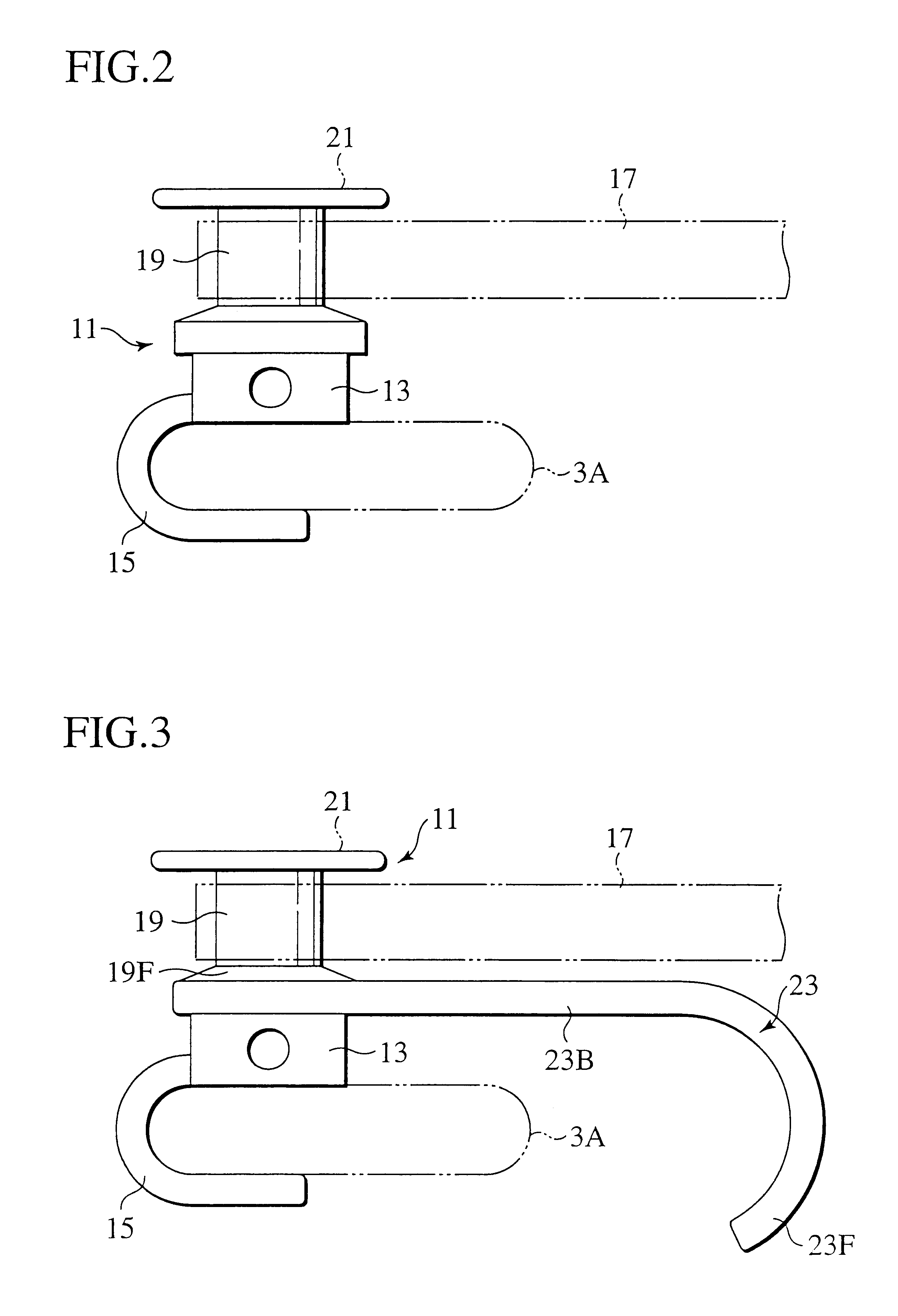
FIG. 2 shows the present invention. An implant 11 includes a block-like implant body 13, an U-shaped curved fixing clamp 15, a pin-like hook portion 19, and a flange portion 21. The fixing clamp 15 is provided to a lower portion of the implant body 13 for supporting a vertebral arch 3A of a vertebra by grasping the vertebral arch 3A. The hook portion 19 having a circular cross section is integrally provided on an upper portion of the implant body 13, and a connecting member 17 such as a wire or cable is hooked over the hook portion 19. The flange portion 21 is provided on an upper portion of the hook portion 19 for preventing the connecting member 17 from coming out.

In a state that the implant 11 is used for hooking the connecting member 17 over the hook portion 19 in the above configuration, since the implant 11 is fixed to the vertebral arch 3A by means of the fixing clamp 15 to support the vertebral arch 3A by grasping it and the connecting member 17 is hooked over the hook porti...

second embodiment

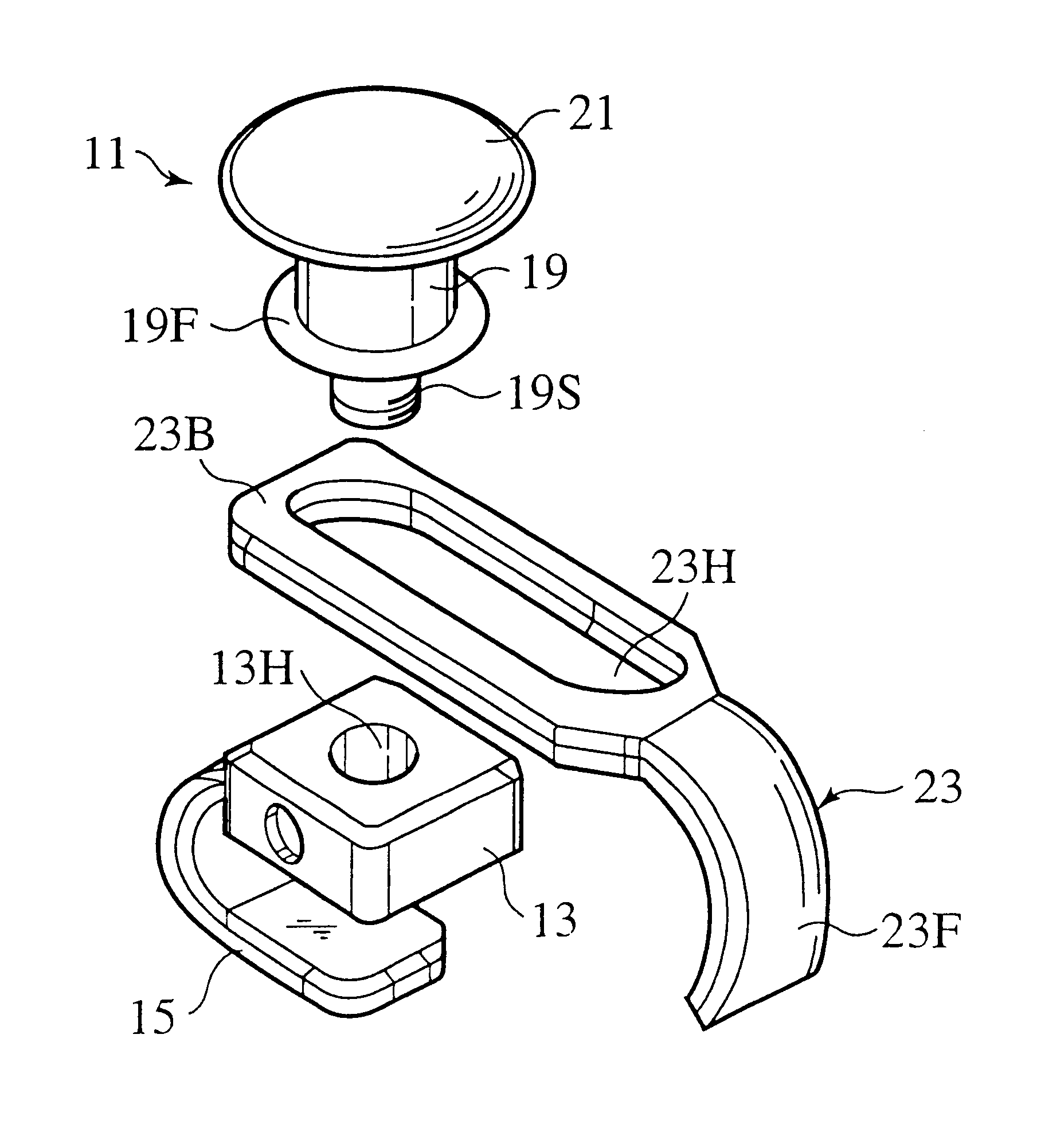
FIGS. 3 to 5 show the present invention. In an implant 11 of this embodiment, a movable clamp 23, which is disposed to be opposed to the fixing clamp 15 and which grasps the vertebral arch 3A, is provided on an upper portion of the implant body 13. The movable clamp 23 can be freely slid and turned or fixed.

More specifically, as shown in FIG. 5, a thread hole 13H is formed on an upper surface of the implant body 13 having the fixing clamp 15, and a thread portion 19S which is screwed into the thread hole 13H is provided on a lower portion of the hook portion 19. The movable clamp 23 includes the curved hook portion 23F on a tip end of a clamp body 23B. Further, the clamp body 23B has a slit or a long hole 23H. Since the movable clamp 23 is disposed to be opposed to the fixing clamp 15, the hook portion 23F grasps the vertebral arch 3A of the vertebra at the opposed side of the fixing clamp 15.

In the above configuration, as shown in FIG. 5, the clamp body 23B of the movable clamp 23 ...


PUM


Abstract

An implant for a bone connector includes an implant body, a hook portion, a fixing clamp and a movable clamp. The fixing clamp has a curved shape and supports a vertebral arch of a vertebra by grasping the vertebral arch. The implant body is provided on an upper portion of the fixing clamp. The hook portion over which a connecting member is hooked is provided on an upper portion of the implant body. Further, the movable clamp, which has a curved shape and grasps the vertebral arch, is provided on the upper portion of the implant body and is disposed to be opposed to the fixing clamp.

Description

CROSS REFERENCE TO RELATED APPLICATIONThis application claims benefit of priority under 35 U.S.C. §119 to Japanese Patent Application No. 2001-233512, filed on Aug. 1, 2001, the entire contents of which are incorporated by reference herein.BACKGROUND OF THE INVENTION1. Field of the InventionThe present invention relates to an implant for a bone connector used for connecting bones.2. Description of the Related ArtWhen connecting bones such as thoracic vertebrae or lumbar vertebrae, the following method has been conventionally employed. A first implant 3 is screwed into centrum 1 such as the thoracic vertebra and the lumbar vertebra. A second implant 4 is screwed into centrum 2. A connecting rod 5 connects the first implant 3 to the second implant 4 as shown in FIG. 1.The first implant 3 includes a screw portion and a head portion. The screw portion is screwed into centrum and the head portion with a large diameter has a rod engaging groove. Also, the second implant 4 includes the sam...

Claims


Application Information

Patent Timeline
Patent Type & Authority Patents(United States)
IPC IPC(8): A61B17/70A61B17/58A61B17/72
CPCA61B17/7022A61B17/7056A61B17/7047A61B17/72
Inventor SHIRADO, OSAMUORIBE, KAZUYATAKAMIDO, HIROSHI
Owner SHOWA IKA KOHGYO
Why Eureka
Try Eureka