Audio device

a technology of audio signals and audio signals, applied in the direction of stereophonic arrangments, instruments, electrical equipment, etc., can solve the problems of large amount of audio signals that must be digitally processed for an extremely short time, large signal processing circuits of a large scale and high speed

Inactive Publication Date: 2005-03-01
PIONEER CORP
View PDF7 Cites 49 Cited by
  • Summary
  • Abstract
  • Description
  • Claims
  • Application Information

AI Technical Summary

Problems solved by technology

However, it is difficult to remove the asymmetric expansion of a sound field as viewed in the horizontal direction.
In the case of using the head related transfer functions, a great amount of audio signals must be digital processed for an extremely short time.
Therefore, the signal processing circuit of a large scale and high speed is required.
Increase of the circuit scale and processing speed is unavoidably imparted on the signal processing circuit.

Method used


Image

  • Audio device
  • Audio device
  • Audio device

Examples


1st embodiment

(1st Embodiment)

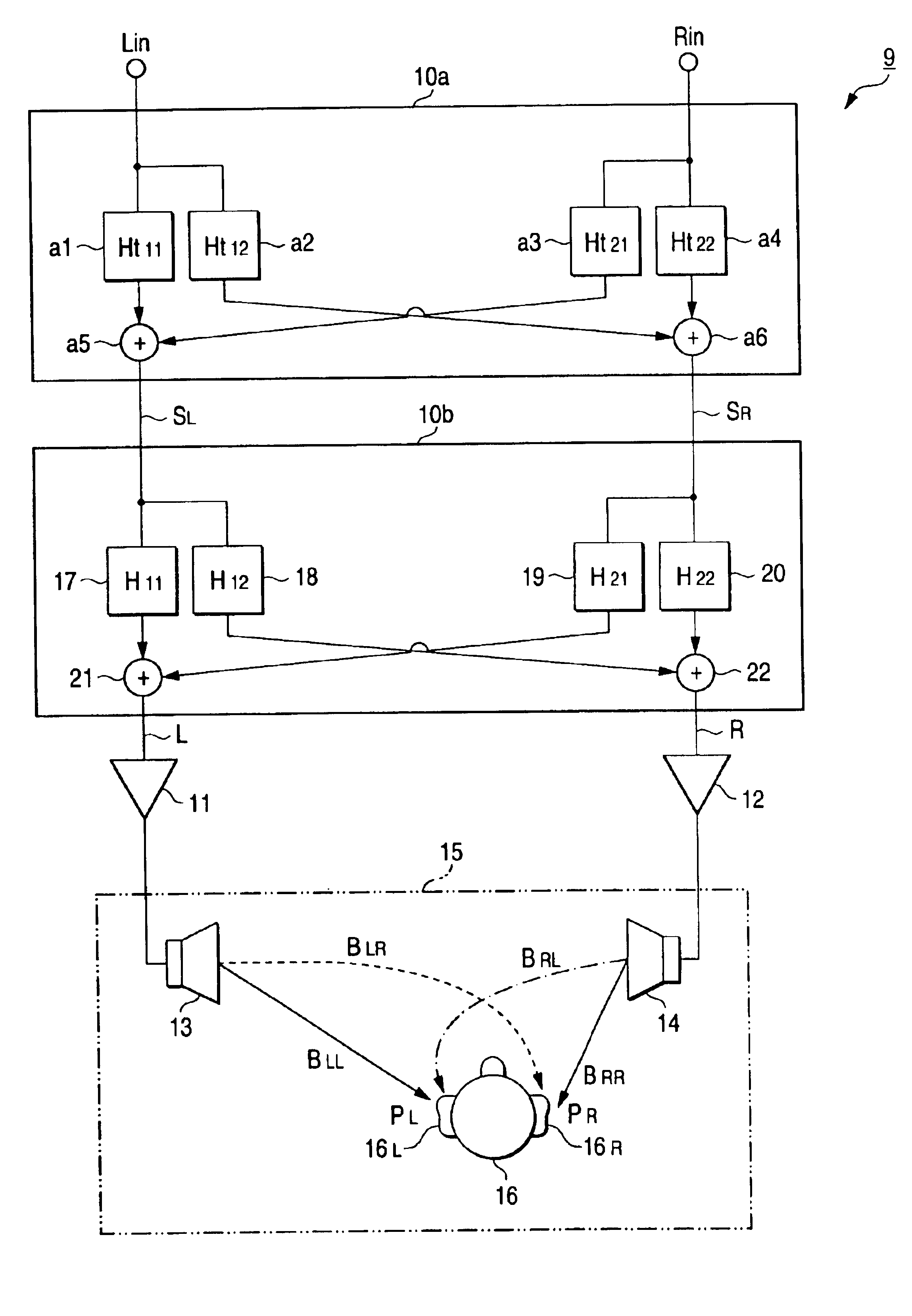
FIG. 1 is a block diagram showing an arrangement of an audio device 9 which is a first embodiment of the present invention. While the invention is not limited to a home use audio device, a car-carried audio device or the like, the invention will be described in the form of a car-carried audio device 9, for ease of explanation.

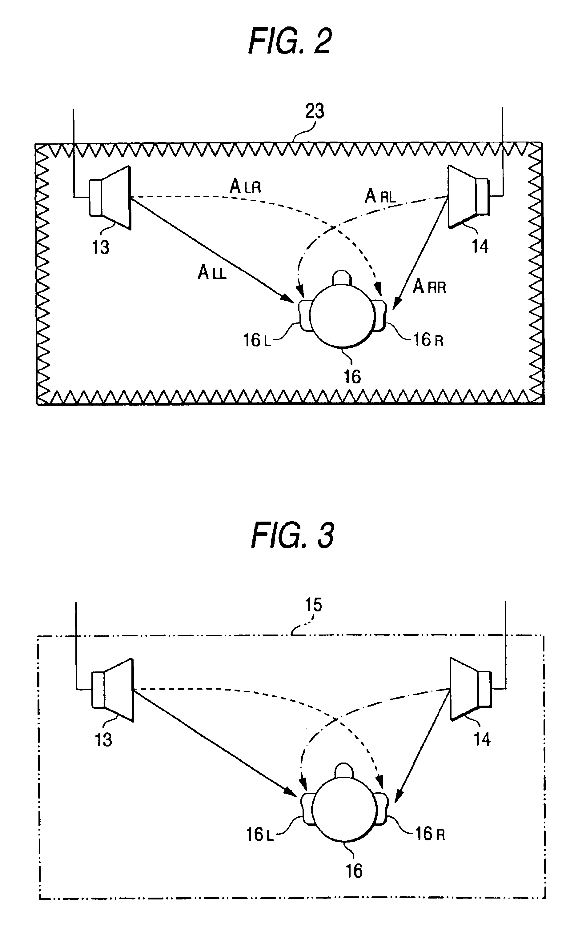
In FIG. 1, the audio device 9 is made up of a head related transfer function (HRTF) circuit 10a, a correction circuit 10b, output amplifiers 11 and 12, and a couple of speakers 13 and 14 attached to the inside of a car cabin 15. The speakers 13 and 14 are located at the right and left positions with respect to a passenger (listener) 16, for example, the right and left side positions on a front dashboard in the car cabin 15 or the front doors.

The HRTF circuit 10a includes operator-circuits a1 to a4 and adder circuits a5 and a6. The HRTF circuit 10a superimposes amplitude / phase characteristics or head related transfer functions, which are equivale...

second embodiment

(Second Embodiment)

A second embodiment of the present invention will be described with reference to the accompanying drawings. A car-carried audio device will be described as a preferred embodiment of the invention.

An audio device of the second embodiment resembles in construction the: audio device 9 shown in FIG. 1.

In the second embodiment, the correction transfer functions H11, H12, H21 and H22 of the operator circuits 17 to 20 are constructed on an algorithm different of the first embodiment. The following method is used for constructing those operator circuits.

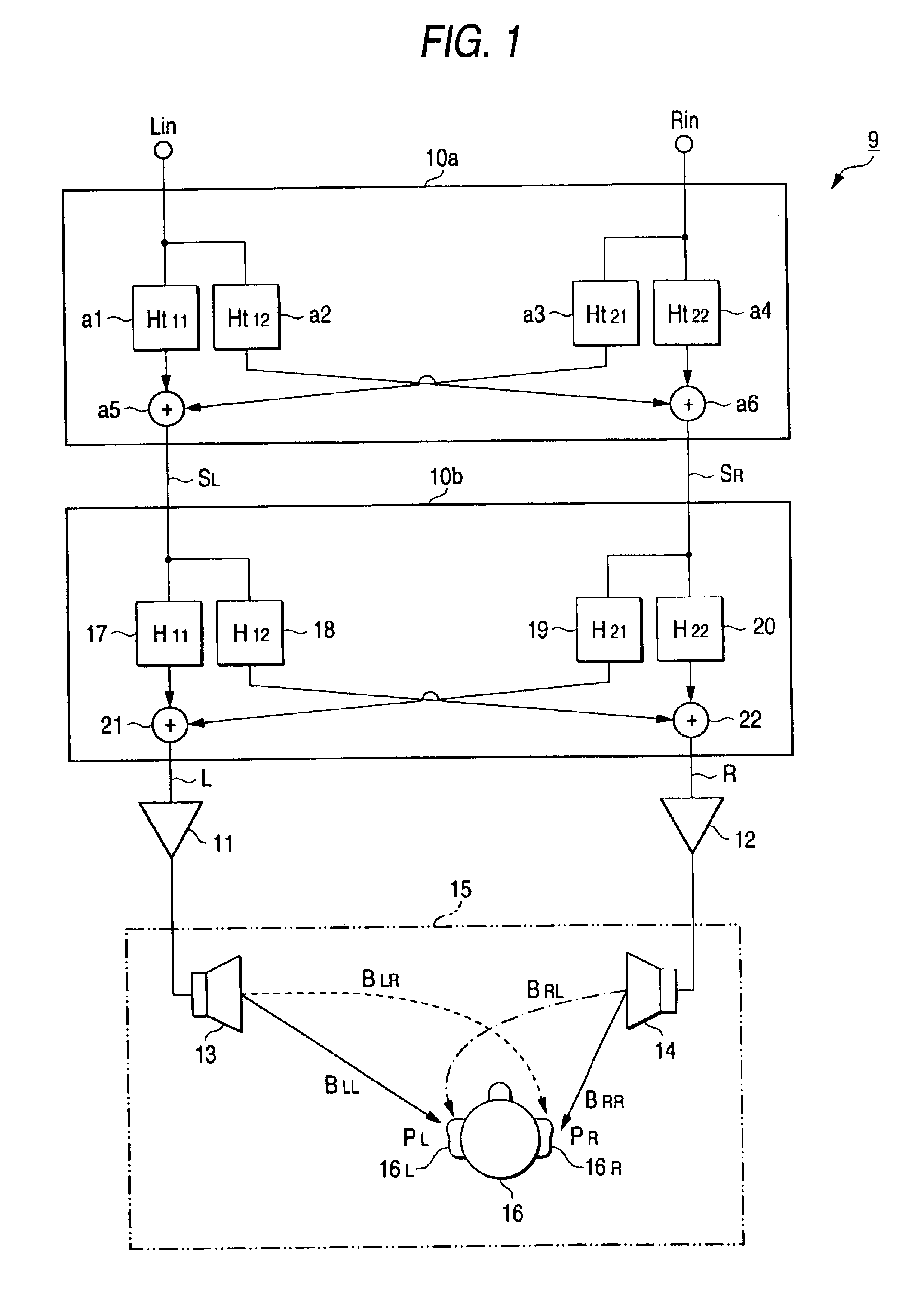
As in the case shown in FIG. 2, a model of: a layout of the speakers, and the listener in the car cabin 15 is formed. A dummy listener 16 and the right and left speakers 13 and 14 are disposed within an anechoic room 23 in accordance with the cabin model. In this state, only the left speaker 13 located in the anechoic room 23 is driven to emit a pulse sound. In this state, only the speaker 13 disposed in the anechoic room ...

third embodiment

(Third Embodiment)

An audio device which is a third embodiment of the present invention will be described with reference to FIGS. 11 through 16. In those figures, like or equivalent portions are designated by like reference numerals in FIG. 1. The audio device of the second embodiment is well suitable for use in a room of a house (e.g., a living room) 200.

In FIG. 11, the audio device is made up of an audio device body 100 placed in a room 200 defining a reproduction sound field, right- and left-channel speakers 101L and 101R, and a remote controller 102 operated by a listener 16 for remote control.

The audio device body 100 may be of the unit type in which a CD and / or MD reproduction device for reproducing a recording medium, such as CD or MD, which contains an audio source recorded therein, may selectively be combined into the audio device body or of the integral type in which the unit or units are assembled into a single frame.

The audio device body 100, as shown in a block diagram o...


PUM


Abstract

A dummy listener and right and left speakers 13 and 14 are disposed in an anechoic room as a model of the layout of those a car cabin 15 or the like. Transfer functions ALL, ALR, ARL and ARR in a space ranging from the speakers 13 and 14 to the right and left ears of a listener 16 in a car cabin 15 or the like are calculated from impulse response series aLL(t) to aRR(t) obtained when pulse sounds are respectively emitted from the speakers 13 and 14. A correction circuit 10b contains correction transfer functions H11, H12, H21 and H22, which are obtained by an inverse matrix of a 2-row and 2-column regular matrix of which the elements are the transfer functions ALL, ALR, ARL and ARR. Audio signals SL and SR on which head related transfer functions are superimposed are applied to the correction circuit 10b, and the output signals of the correction circuit 10b are supplied to the speakers 13 and 14.

Description

BACKGROUND OF THE INVENTIONThe present invention relates to an audio device which corrects a delocalization of a center sound image or an asymmetrical expansion of a sound field in a reproduction sound field, such as a car cabin or a listening room, to thereby provide a natural sound space to listeners.In a conventional audio device, right- and left-channel speakers 5 and 6 are disposed in a reproduction sound field space 4, such as a listening room, as typically shown in FIG. 17A. When a listener hears a stereophonic sound or the like at the center in front of the speakers 5 and 6, a center sound image C, such as vocal, is localized in front of the listener. When the listener listens at a position asymmetrically located with respect to the speakers 5 and 6, the center sound image C is delocalized, thereby failing to produce a natural sound field space.A car-carried audio device is known as a typical case where the center sound image C is likely to be delocalized. The car-carried au...

Claims


Application Information

Patent Timeline
Patent Type & Authority Patents(United States)
IPC IPC(8): H04S7/00H04R3/04G10K15/00H04S1/00
CPCH04S7/302H04R2499/13H04S2420/01
Inventor MAKINO, ATSUSHI
Owner PIONEER CORP
Why Eureka
Try Eureka