Mounting a fuel vapor management valve internally to a gas tank

a technology of fuel vapor management and gas tank, which is applied in the direction of functional valve types, liquid fuel feeders, machines/engines, etc., can solve the problems of difficult installation of valves and valve calibration, and achieve the effect of simple and effective, yet relatively low cos

Inactive Publication Date: 2005-03-08
EATON CORP
View PDF4 Cites 32 Cited by
  • Summary
  • Abstract
  • Description
  • Claims
  • Application Information

AI Technical Summary

Benefits of technology

The present invention provides a solution to the above-described problem of installing a fuel vapor management valve, particularly one of the type having a plastic body, in the interior of a metal fuel tank without the need for separate fasteners. The method of the present invention enables a single valve design to accommodate tanks of various depths and has provision for limited adjustment of the vertical position of the valve within the tank to permit variation in the fuel level at which the valve closes and prevents vapor from escaping from the tank.
The present invention thus provides a simple and effective, yet relatively low-cost way of attaching a fuel vapor management valve to an access opening cover for a fuel tank in a manner to selectively position the valve within the tank and to accommodate various different depths of fuel tank without requiring a change in the design of the vapor management valve.

Problems solved by technology

This arrangement has rendered it difficult to install the valve and calibrate the valve at the correct height within the tank and has required individual valve structures for tanks of different depth configuration.

Method used


Image

  • Mounting a fuel vapor management valve internally to a gas tank
  • Mounting a fuel vapor management valve internally to a gas tank
  • Mounting a fuel vapor management valve internally to a gas tank

Examples


Embodiment Construction

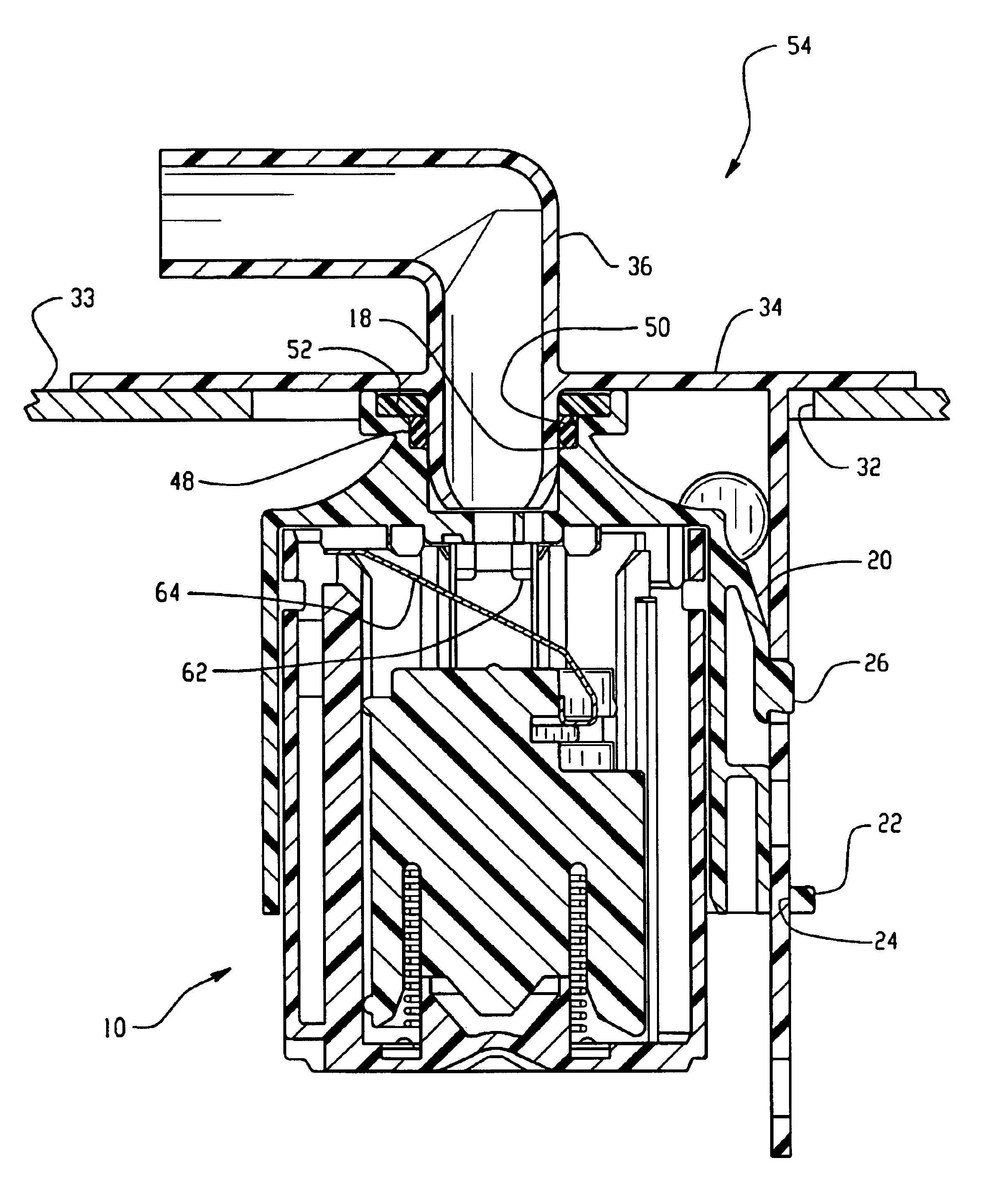
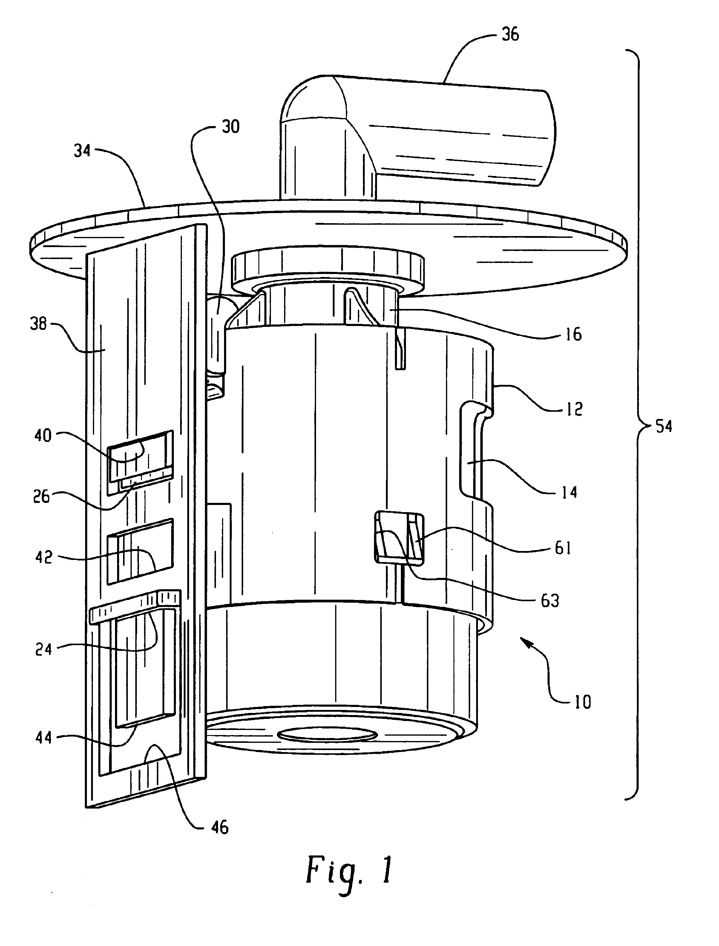
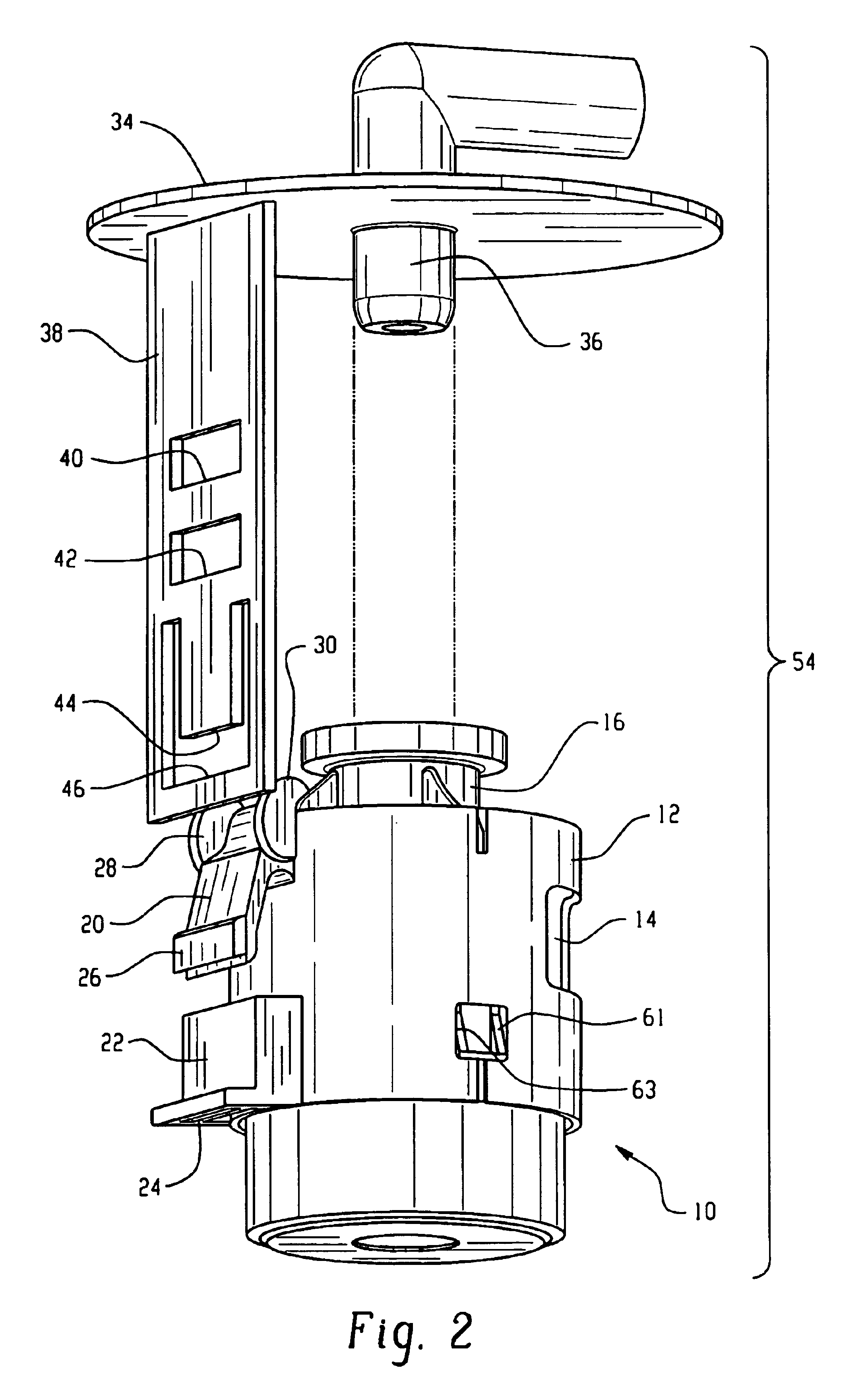
Referring to FIGS. 1 through 3, a vapor management valve indicated generally at 10 has a body 12 formed generally of plastic material with at least one inlet aperture 14 and an outlet fitting 16 formed on the upper end thereof with a vapor outlet passage 18 formed therein.

The valve body 12 has a pair of lugs or projections 20, 22 formed on the exterior thereof in generally vertically spaced aligned arrangement with the lower projection 22 having an aperture therein in the form of a rectangular slot 24. The upper projection 20 is in the form of a resilient finger or tab with a lug or tab 26 extending outwardly from the end thereof for snap-locking engagement as will hereinafter be described. In the presently preferred practice, projections 20, 22 are molded integrally into body 12, but may be formed separately and attached thereto.

The valve body further has at least one and preferably a pair of outwardly extending spaced standoffs 28, 30 extending outwardly therefrom and located vert...


PUM


Abstract

A plastic bodied fuel vapor management valve has mounting lugs thereon which are adjustably snap-locked onto a bracket provided on a cover for the tank access opening to selectively locate the valve vertically on the bracket. As the valve is engaged with the bracket, a vapor vent fitting provided on the cover is received in the valve outlet and sealed by a seal ring. The cover preferably comprises a mounting flange for a fuel level signal sender.

Description

BACKGROUND OF THE INVENTIONThe present invention relates to mounting of fill vapor management valves in a gas tank and particularly relates to the mounting of such valves in a metal fuel tank. Such valves are typically float operated formed of plastic material and provide for a valve outlet which conducts fuel vapor out of the tank through a conduit to a storage device such as a canister filled with carbon particles. Heretofore, where such valves have been mounted internally in the tank, it has been necessary to attach the valve to a cover member for the access opening through which the valve is inserted in the tank. Known arrangements have provided for attachment of the vapor management valve to a metal cover, such as the fuel level signal sender mounting flange, with clips and fasteners. This arrangement has rendered it difficult to install the valve and calibrate the valve at the correct height within the tank and has required individual valve structures for tanks of different de...

Claims


Application Information

Patent Timeline
Patent Type & Authority Patents(United States)
IPC IPC(8): B60K15/035B60K15/03B60K15/01F02M37/00
CPCB60K15/03519B60K2015/03467Y10T137/0874Y10T137/3099B60K15/01
Inventor MCINTOSH, ANDREW W.SPINK, KENNETH M.
Owner EATON CORP
Why Eureka
Try Eureka